
How to Build a Deck (with 120+ Pics, Diagrams, Pro-Tips, & Helpful Links)
May 25, 2016 | by Ethan (email) |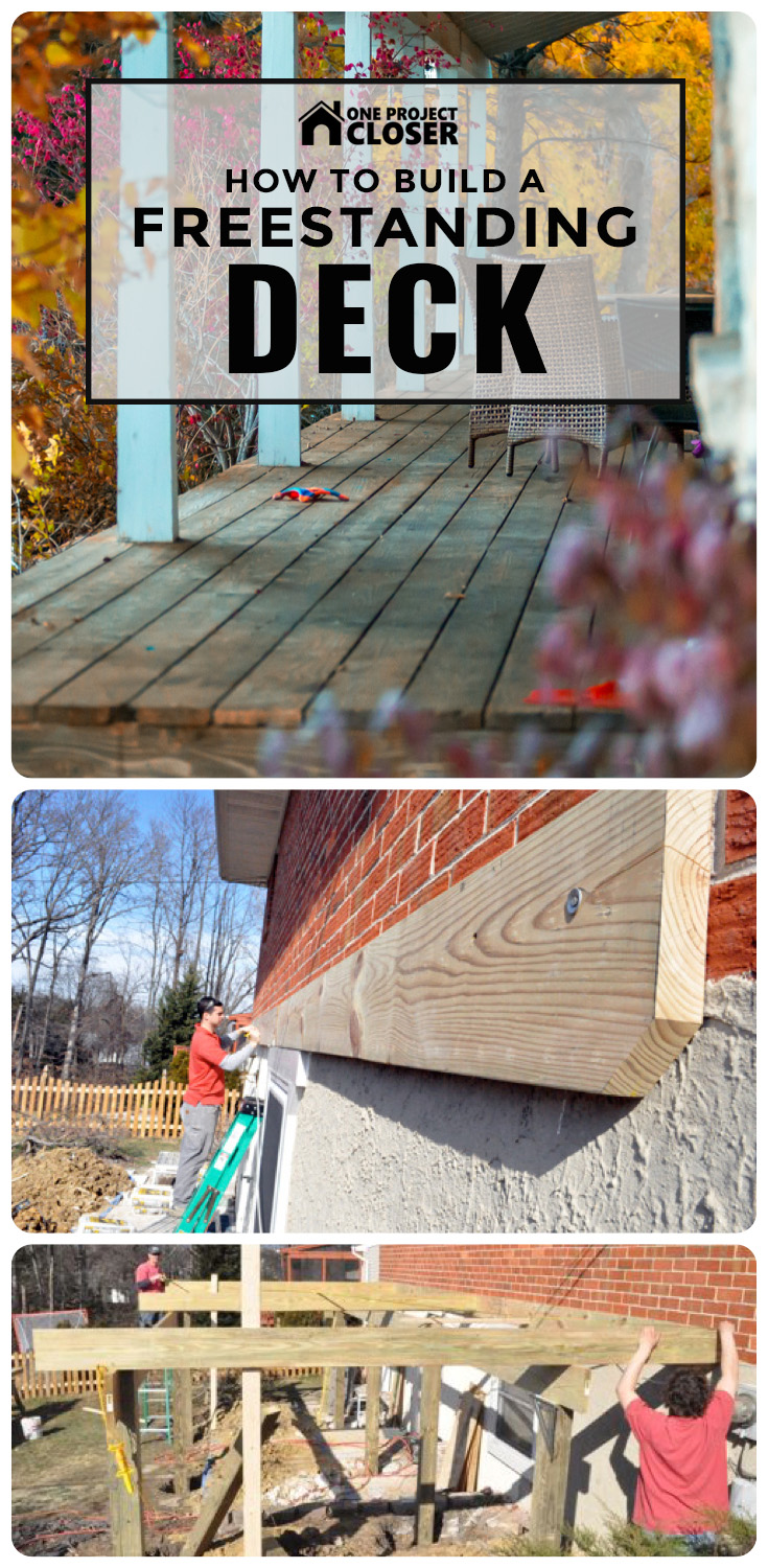
If you’re a regular reader, you know this detailed guide is the culmination of many days shadowing expert general contractor and carpenter Steve Wartman. I was on-site as he and his crew built this deck, taking pictures of the progress, documenting the work and discovering tips and tricks. I’m convinced that there’s no better way to learn how to tackle home improvement projects than following a licensed contractor through a build. If you enjoy this article, check out our other Project Guides. To stay current on all our Pro-Follows, subscribe via RSS or email.
If you live in the greater Baltimore area and are considering adding a deck to your home (or any other sort of home improvements), I suggest you give Steve a call. This article is a great example of the high quality and professionalism that Steve and his crew bring to every job. For more examples, check out our articles on building a shed or how to hang drywall.

How to Build a Freestanding, Composite Deck
The same homeowners that had Steve’s crew build a custom shed have contracted him again to construct a new, composite deck on the back of their home. They went with Trex brand composite materials for the build, because Trex is virtually maintenance free, meaning the homeowners won’t ever need to seal, brighten or strip the decking boards.
The Plan
Here’s Steve to give you a short introduction to this project.
Video Summary: Steve describes a plan to build a new, 12 x 24′ deck and a 4′ set of stairs. It’ll have two rows of buried posts, Trex composite decking, Trex trim boards and a white vinyl rail system.
Step 1: Plan, Dig and Pour the Footers
Determining the location of the deck was easy. It was more difficult to determine how many footers were required and where they were going to be located. This video shares some details about footer and ledger board requirements.
Video Summary: How the deck attaches to the house is one of the factors that determines the required number of deck posts and footers. Other considerations include the size and shape of your deck, how much weight it will hold, and the size of the beams. This deck is rectangular in shape, and the homeowners aren’t planning on adding a hot tub (or other heavy objects). Since Steve’s crew couldn’t through-bolt the ledger board, they’ve installed two rows of posts, creating a “free-standing deck.”
The first row of posts was placed 3′ off the house, and the second row of posts was 8′ after that. Posts are spaced no more than 8′ apart so that means we have four posts per row, with the first row having 1 additional post to account for the stairs. Here’s a sketch of the deck and posts.

After Steve determined the footer locations, the crew ran several string guides and started digging. This was no small task because they decided to cut through the brick patio and underlying concrete before learning it was 5-1/2″ thick.


Each footer needed to be deeper than the frost line, and here in Maryland that means footers must be at least 30″ deep. In areas such as northern Minnesota, footers need to be at least 60″ deep, so check the code for your area before digging. Steve’s crew dug each hole about 24″ across. Before continuing, all the footers needed to pass inspection. In this jurisdiction, this was the only required interim inspection, and the checklist includes:
- there are a sufficient number of footers to properly support the deck
- the footers are spaced appropriately
- the footers are dug to the proper depth (30″), which is the depth required to be below the frost line in this region
Pro-Tip: Before you start digging, have underground lines (water, gas, power, communication, etc.) located. Call the North America One Call Referral Service (1-888-258-0808). It’s free and required by law.


The inspection went smoothly, and Steve’s crew started pouring the footers. Using 80lb. bags, they mixed enough concrete to achieve an 8″ thick pad.


They used a garden hoe to make sure the concrete would set with a nice, flat surface.

Step 2: Install the Ledger Board
While the concrete cured, the guys started on the ledger board. They installed a 2 x 10′ ledger along the entire length of the deck, taking care to ensure it was completely level. Steve and his crew temporarily secured it in place using a powder charge nailer. Here’s a quick demonstration:
Video Summary: In the video, Steve shares how driving temporary anchors makes it easier to install the ledger board. For this brick and masonry house, you have to use concrete fasteners, and a powder charge gun actually uses a .22 caliber shot to quickly drive the anchor. It’s important to pre-drill a hole so you don’t split the board which also enables the nail to go further. That’s how they temporarily set their ledger board.
Next, the crew marked the locations of their joists. Often you’ll see joists spaced at 24″ on center (oc); however, with composite decking, joists need to be closer together. Steve’s crew marked their joists at 12″ oc. Predetermining the joist locations ensured that none of the concrete anchors will create an obstruction, and it allowed them to place an anchor in every bay (between each joist).


The crew used concrete anchors called Red Heads to secure the ledger board.

The concrete anchors needed to be staggered and, for the upper row, driven into the mortar between bricks. For each Red Head, the guys pre-drilled a hole, used a hammer to drive them in place, and a socket wrench to tighten them down.


Step 3: Install Deck Posts and Beams
The crew used pressure treated 6 x 6″ for posts on this deck. These were rated for “ground contact”, which, as you might expect, means they can be buried directly in the ground.
Pro-Tip: Pressure-treated lumber is infused with chemical and rated by the amount per cubic foot of wood. Ground-contact lumber has .40 pounds of preservative per cubic foot, and above-ground rated lumber has .25 pounds.
Pro-Tip: The size of posts required for a deck installation depends on the span being supported by the post, as well as the height of the deck. Steve’s crew prefers 6 x 6″ posts for their sturdiness; however, 4 x 4″s may be used in certain low-height installations. In certain very tall installations, cross-members may be required between the posts for added support and to prevent racking.

The challenges with installing deck posts include keeping each post:
- square with the house
- square with all other posts
- the right distance from the house
- notched at the proper height to support the beams and joists, ensuring an adequate slope away from the house
The crew moved the first post into place and marked a line indicating the very top of the post which was even with the support beam. The reference point on the ledger board was the bottom of the floor joists.

Using a circular saw, they cut the post to the proper height, based on the previous measurement.

Using a reciprocating saw, the crew cut a notch for the support beam so that the top of the post was flush with the support beam.

The support beams consisted of two, 2 x 10″ boards nailed (and later bolted) together, side-by-side in the notch.

Pro-Tip: You may see support beams where the deck post is sandwiched between two pieces of 2x material. The method we describe here is better, because when the two boards are touching, they act as a single unit. Furthermore, separating the 2x material requires additional blocking in between the joists to support bolting, and therefore, longer bolts.
With the post cut to the appropriate dimensions, the crew moved it into place, and secured it with temporary boards. This was a tedious activity that required several pairs of hands and repeated measurements, but it was extremely important for the finished product.

The crew repeated the process for the middle post, and, after it was in place, added one of the 2 x 10″s that will makeup the support beam. This allowed them to double-check level and distance from the house across the entire gap, and make adjustments as needed to each post.

Again, the level was aligned just like a floor joist so that the top of the floor joist sat flush with the top of the ledger.

This process continued for all five posts in the first row along the house. The middle post was where two support beams butted against each other. The transition was accomplished by equally dividing the space in the notch between the two beams.


In this picture, you can see all the temporary boards that kept the posts and support beam in place.

Once the crew was satisfied with the entire row, they back filled the dirt and tamped it down, taking care not to move the post. Any movement required additional measurements to ensure nothing moved out of square with the house or the other posts, and that the post was still at the proper height.


The second row of posts went in much the same fashion except for one thing. Since the crew had the ledger and first row finished, they added a few joists and ran a string guide to make it easier to setup the rest of the posts. It’s also important to note that they established a 3/8″ slope (over the entire width) to direct water away from the house.


Once the crew had set a few more posts, they ran a tape measure along the diagonals to check for square.

This picture shows a crew member adding that second 2 x 10″ to form the support beam.

These two beam components were later secured with staggered carriage bolts through the post.

Step 4: Install Floor Joists
Since the ledger was already marked, lining up the joists was not a difficult task.

Here you can see the crew once again made sure the joists were square to the ledger. The importance of re-checking square measurements cannot be overstated in a deck build. If components start out of square, it will be hard to make the deck look good at the end.

Pro-Tip: Joists should always be placed “crown up” in an installation. All joists must be oriented identically in this manner to ensure the deck won’t have waves between the joists. In our tutorial on How to Build a Shed, we provide a video on checking and marking dimension lumber to identify the crown.
The crew did break out a planer at one point because they found a few boards were thicker than the others.
Pro-Tip: Double-check board dimensions, because you may find some variation in your lumber package. Never assume that all joists are exactly the same dimensions. Purchasing extra lumber allows you to be more choosy and avoid using bark-cut or bowed boards.

Each joist was toe-nailed in place with four nails, and then a Simpson hanger tie was added.


It was fun to see the crew use this palm nailer for fastening the hanger ties. It made driving the 10 nails into the hanger very quick–much quicker than could be achieved with a regular hammer, which is an acceptable (albeit much slower) alternative.

The guys used Simpson nails with the hanger ties. The shorter nails (N10) secured the hanger to the ledger, while the longer nails (10d) were used for the angled slots. Using the correct nails for hanger ties is very important, as the strength of the hanger is dependent on using the appropriate hardware.

As you may remember, the crew planned the joist spacing at 12″ oc since they were installing a manufactured composite decking surface. For traditional 5/4 pressure treated wood surface deck, 16″ oc is more common. Joist spacing depends on both surface material as well as spanning distance between the posts.
Pro-Talk: The term “5/4 lumber” is shorthand for lumber that is nominally 1.25″ thick (or 5/4s of an inch). 5/4 lumber is actually finished to 1-1/16″. The type of 5/4 lumber used on decks has rounded edges and is known as “decking board”. Composite decking material is generally the same size as 5/4 lumber (or close to it).


Pro-Tip: Overhead power lines must have at least 10′ of clearance. These lines will later be buried to meet that requirement.
Step 5: Add the Band Board to the Joists
The crew got all the joists set in place and secured with joist hangers, including a double-joist in the middle. Since the deck was 24′ long, the band board consisted of two 2 x 8″s butted against each other, and the transition at the double joist.

Using a string guide, the guys marked the ends of each joist and cut away the excess with a circular saw.

The band board was situated between the rim joists and secured with four nails per joist. Note that the last joist was 1.5″ longer to remain flush with the band board. This allowed nailing from the side of the joist into the board.

Pro-Talk: A rim joist, or band board, is the final joist that caps the end of the row of joists that support a floor.
Step 6: Install Blocking Between the Joists
Blocking in between the joists provided a surface to mount the rail system. This was especially important because they planned to “picture frame” the perimeter to conceal the cut ends of the composite deck boards. To achieve this, the crew cut pieces of 2 x 4″ to fit in between joists and sistered a 2 x 4″ along each rim joist.


Step 7: Build the Stairs
Building the stairs was not an overly difficult process; the key to success was making accurate cuts. In this short video, Steve shares how he calculated the stair stringer dimensions.
Video Summary: Steve describes how he started the process to build the stairs by first determining the total height of the stairs. Stair risers need to be between 7 and 7-3/4″ tall, and using 7-1/2″ translates into 12 risers. Likewise, stair treads need to be between 10 and 11-1/4″ wide. Since they will have 12 steps, the tread needs to be 10-1/2″ with a 3/4″ overhang. If this still seems confusing, Todd from Home Construction Improvement has a very simple Stair Stringer Calculator spreadsheet you can download for free.
With the rise and run dimensions calculated, it was time to mark the stringer. Watch this short video for more information about marking the 2 x 12″.
Video Summary: This video shows how to scribe the stair stringers. It’s important to check the crown of the board and make sure it’s “crown up.” Using a framing square, line up the rise and run measurements on the edge of the stringer and mark your line. Then you move down and repeat the process. Lastly, extend the first line (riser) through the 2 x 12″ and cut off the excess.
I put together these diagrams to help visualize the stringers. You’ll notice that the very last step is 1″ shorter. That’s because there are no deck boards on the concrete, and shortening that riser keeps each step height consistent.


The stairs measured 4′ across and to maintain the 12″ oc supports they will needed a total of five stringers.

The two outside stringers were slightly longer so that the cross member was situated in-between them. The inside stringers butted up against the cross-member, and this was important because it allowed Steve’s crew to drive nails in two dimensions for a more secure hold.


These pictures show how the guys assembled the stairs.


In the diagram above you see mention of a concrete pad. It’s important to have something solid at the bottom so the stairs don’t just sit on the ground which will erode over time. While building the stairs, the guys also built a concrete form and poured a small concrete pad.

This pad had two “footers” where the stair rail posts will be situated.


Here are a couple of shots showing the stair landing. It measured approximately 4 x 4′, and the joists and band board were installed just like the rest of the deck.


After the concrete cured, they moved the stairs into place with the top of the stairs resting on the deck support beam.


Steve’s crew checked that the stringers were level and then nailed them in place.


Step 8: Flash the Ledger Board
Contractors use flashing to prevent water and moisture from finding their way into a home. The general idea is that since water flows down with gravity, you can overlap waterproof membranes (like siding, stucco, metal flashing etc.) that will direct water away from the house. Improperly flashed decks can cause a lot of problems, because leaks may not be visible right away, and they are not always readily diagnosed. Furthermore, making repairs after a deck is finished can be a very onerous task. (Although some deck construction methods make it easier to address such challenges than others. We talk about that below.)
The Unique Situation with this Deck: The exterior of the house is a combination of brick and block. The ledger board was fastened to the brick, which is already constantly exchanging moisture with the outside world. Since the masonry anchors Steve used did not penetrate deep enough into the brick to disrupt the moisture barrier, Steve’s crew was confident that this deck did not require separate flashing. (There is no path for water to enter the home.) Typically, the crew would err on the safe side and flash anyway; however, in this installation flashing would have been visible and would have detracted from the look of the finished product.
This situation with this deck is unique because the ledger board in this design was not a load bearing element. This deck is freestanding, with two sets of posts and beams on which the joists sit. In most decks, the ledger board is load bearing, and the bolts go all the way through the rim joist of the house. This situation always requires flashing to prevent leaks, and it’s recommended that holes drilled for bolts should be filled with a silicone sealant. Look for helpful links including 2012 International Building Code (IBC) and International Residential Code (IRC) in our Related Content section at the end of the post.
If the crew had decided to flash the deck, here’s how they would have done it:
- Trench out one of the horizontal mortar joints above the ledger board enough to insert an inch of copper flashing.
- Before inserting the flashing, bend a small double-back hem that will act as a wedge between the bricks.
- After inserting the flashing, seal the joint with a flexible sealant.
- Make sure the flashing extends down over the ledger board.
- Cut the flashing at each floor joist in order to get the flashing between joists to bend.
Pro-Tip: Newer chemicals for pressure treated wood like alkaline copper quaternary (ACQ) and copper azole, are more corrosive, and aluminum flashing and steel z flashing actually deteriorate when in constant contact. For that reason, use a rubber or copper flashing product. One reader also suggests using 1.5″ wide strips of #15 building paper between the two can also prevent problems.
Step 9: Lay the Composite Deck Boards
Steve’s crew installed Trex Transcend composite decking boards for this build. The homeowners were really excited about this, because composite decking is almost completely maintenance free. They won’t ever have to worry about sealing, stripping or brightening the boards. The band board and stair risers will be wrapped in a white, Trex composite trim.

Trex is a capped-stock, which means the core of the board is composed of a different material. For that reason, exposed ends are especially undesirable, and Steve’s crew created a “picture frame” around the perimeter to conceal the board ends.

The guys knew that the house wall was not 100% straight so they ripped the first piece of Trex in such a way as to eliminate as much inconsistency as possible.

They cut a 22.5° scarf joint to conceal the transition from one board to the next.
Pro-Talk: A scarf joint is made by overlapping two pieces of wood along a tapered, beveled, or chamfered end.


Steve’s crew used screws designed for composite decking. If you look closely, you’ll notice that the top is reverse threaded which holds the screw in place while the screw-head acts as more of a plug.


Screwing down the deck boards was slow going because each screw needed to be pre-drilled to prevent the board from becoming disfigured. Besides the added cost of materials themselves, this step made the installation of composite decking more expensive than the installation of traditional pressure treated products.

After the guys set two adjacent pieces of the “picture frame” in place, they started laying the diagonal boards. It was important that the first board be laid accurately, because they acted as a point of reference for all of the others.

Steve’s crew cuts the end at a 45° and measured the opposite side to ensure the angle stays true.

Each board was secured with two screws at every joist.

Pro-Tip: You can opt for hidden fasteners that are driven into the side (rather than the face) of the deck boards. This requires a specialized jig and incurs some extra cost.
All decking (composite and traditional) will expand and contract with changes in weather, and it’s important to adequately space each board to provide that necessary room. To achieve a uniform spacing, Steve’s crew sets up a block with 8d nails to create the gap.

This picture shows the progress after a few rows have been laid.
Pro-Tip: Trex composite features a wood-grain inlay to make the boards look more like a natural product. The wood grain is a pattern that you’ll see repeated many times over the length of a single board, and if you’re not careful to stagger the pattern, it will be readily apparent to anyone looking at the deck.

After the diagonal boards were in place, these ends were trimmed with a circular saw.

Pro-Tip: Even though I describe this as a 12 x 24′ deck, it will actually measure a few inches shy of 12′. If the homeowners had truly wanted a 12′ deck, it would require Steve to purchase 20′ composite boards since they’re being installed diagonally, and that jumps the price up significantly. By making the deck just a little shorter, Steve can purchase 16′ composite boards and provide a more cost-effective solution.
Here are some images that show how the deck progressed.


They snapped a chalk to mark their line for the circular saw.


Step 10: Install Trim on the Band Board and Stair Stringers
Steve’s crew installed a white, 2 x 12″ PVC trim board on the outside stair stringers and the band board. It gave the deck a nice, polished look and matched the rail system. PVC is nice to work with because it’s lightweight, flexible and maintenance free. The guys mitered all the corners and used finish nails to fasten the boards.


They filled all the nail holes with a PVC putty so that you can’t even see the nail hole.

To cut the PVC to match the stair stringers, they cut the very first riser and temporarily tacked the PVC against the stringer for marking cut lines. This was better than re-drawing the stringers because even the most accurate carpenter may have some variation, and this ensured that each section matched perfectly.
Editors Note: We are walking through this deck build chronologically, but stair stringer trim is best left after the treads, risers and stair guards have been installed.


PVC is easy to cut, so a jigsaw makes short work of cutting out the stringer trim.


Step 11: Add Stair Treads and Risers
After getting the trim in place, the guys moved onto the stair treads and risers. Every three or four steps, they added blocking to ensure a consistent width.

Steve’s crew also added these blocks at the base, which will have concrete anchors driven into the small slab below. The two outside bays don’t have blocks because they’ll have stair posts (eventually).

Starting at the top, the crew measured the riser first, cutting a piece of PVC long enough to reach across the cut edges of the stringer trim.


Next, the crew cut the first tread. You can see how that the tread does not extend the entire length. This is on purpose, because the crew left room for a return piece to conceal the cut edges of the tread.

This picture shows one of the return pieces that hasn’t been fasten yet. It was slow going to get all the cuts exactly right. To help themselves out, the guys put together templates. The return pieces were secured with screws through the side of the return and into the tread board.

Another small detail that you might have missed is that the guys notched out the stair riser for the return piece using a Bosch multi-tool. This notching makes the tread appear to go under the riser when viewed from the side, which creates a nice visual look on the staircase.


Step 12: Install the Composite Rail System
Steve’s crew installed a white, vinyl rail system, and the picture below shows one of the steel posts and plastic spacers.

Remember the blocking between joists around the perimeter of the deck? That blocking allowed Steve’s crew to securely fasten the steel posts with 3-5/8″ LedgerLOKs. Each post was leveled as necessary with shims, ensuring it was perfectly vertical before fastening. After the LedgerLOKs were installed, each post got a plastic spacer which serves as a guide for the PVC trim cover.
Pro-Tip: The International Residential Code (IRC) requires rails to resist a load of 200 pounds.


Next, the guys trimmed the vinyl sleeve to the appropriate height and slipped it in place with another plastic spacer at the top. They placed posts about every 6′.
Pro-Tip: Deck railings are required to be at least 36″ tall.


Here’s a picture of one of the post caps. These were installed last and are usually glued in place to avoid using fasteners.

After the posts were set, the guys slid a square, base trim piece over the vinyl sleeve to conceal the bottom of the steel post. Next, they cut the lower rail to length and screwed it in place. It’s important to cut an equal amount from both sides of the rails to maintain a balanced appearance for the pickets.
Pro-Tip: The lower rail should be low enough that a 4″ sphere cannot fit underneath the rail.


This rail system had convenient mounting brackets for the upper and lower rails which included plugs and caps to conceal the screw heads. After the lower rail was fastened, they inserted a picket into each hole.

The upper rail was installed in a similar fashion, except for one additional step. The upper rail had an aluminum channel for increased strength, and Steve’s crew needed to trim this channel to length.


The guys placed 4 x 4″ pressure treated posts at the bottom and middle of the stairs. The set at the bottom rested on the concrete pad and were through-bolted in place.

The middle set ran all the way into the ground where they were secured much like the deck posts: a 30″ deep hole, concrete footer, and backfilled with dirt. They also through-bolted these and had to notch the stair treads.


Each post was cut at 36″ and a vinyl sleeve was fit overtop.

The stair kit had angled brackets. However, the guys needed to cut the hole for the picket.


Steve’s crew cut the upper and lower rails at a 35° angle, and trimmed them to length with equal portions cut from both sides to maintain an even appearance. The holes on the upper and lower rails were slightly bigger to allow the pickets to stand plumb.


Code requires a continuous handrail so they added this metal-core rail on the right side to meet that need.


Final Pictures
Here are several pictures of the finished product. This deck looks fantastic, and will be excellent for entertaining and enjoying the outdoors.


Special thanks to readers Jeff Williams, Icarus, Haus356, William, MissFixIt, Joe, Jake, Eek565, JD, Reuben Collins, Simon, and John. Without great questions and comments, this how-to wouldn’t be nearly as complete.

This looks awesome! Great job on the pro-follow, Ethan! The pictures and explanations really give me a good idea of this project and its complexities.
One question, do you plan to follow up with homeowners some time after a pro-follow to see what their thoughts are? I’m not looking for a Angie’s List impression (“he was good – would hire again”) but rather something more technical (“doing XYZ was a great idea because it serves ABC purpose much better”). I realize not every homeowner may be technically-inclined, but for the ones that are, it’d be interesting to hear from.
That’s not a bad idea. I actually know this homeowner (randomly) so it wouldn’t be a problem to check in with him down the line, see how the deck is holding up.
Just in time for grilling season to start. 🙂
It’s a shame that over engineered (IMO anyway) building code sometimes trumps aesthetics. I’m not a fan of the extra continuous handrail, but I guess there’s no real good way around that.
I agree the extra handrail looks kind of awkward and seems kind of superfluous. Is that requirement part of the national building code or a local thing? And is it a newer requirement? My deck was built 3-4 years ago and our railings look exactly the same as these, but I don’t have an additional handrail. My stairs are configured differently (come down halfway to a landing and split off in two directions), which may be a factor.
While I get the aesthetic arguments against it, I actually think this railing may be better for helping mobility-impaired folks navigate the staircase. It’s not something I would want/need, but I can understand that an elderly person might appreciate having this available to them.
I didn’t like it much either. Maybe there is a rail system that accounts for this and can make a more integrated look. I’m not sure when this became a requirement (maybe 2009 IBC). I’ll investigate.
Good job. As Simon suggested, It would be nice to revisit this deck in a couple of years to see how it holds up and weathers. Perhaps a piece on maintaining it?
This was a great project to see come together. I love this pro-follow series. Can’t wait to see what you do next.
Thanks Reuben! I’ll be updating everyone on the basement remodel next, and I’m trying to line up the next pro-follow after that. I’ll let you all know when it’s finalized.
it seems strange that there is a disconnect between the stair railing and the rest of the railing around the deck… was there any way to make it continuous?
Overall the final product looks very nice! I am sure that it will get a lot of use once there is a door to it from the house 🙂
Lol, good eye, Joe. I haven’t noticed that before either, but now that you mention it, it looks a bit funny.
If the stairs were a bit more separated from the rest of the deck, they could have run railings between them. Instead, they opted to maximize the space and that results in two posts right next to each other.
Hehe…. a door will definitely help. The plans for the in-law addition have hit a snag (zoning) so I’m not sure when that’ll move forward. I’d guess the door will be one of the first things when that gets underway.
I have seen this on a few other composite decks around here, my parents’ being one. The problem is caused by the way a composite railing on the stairs is run… on my deck, which is just wood, the railing closest to the deck itself (and high up on the staircase) is actually fastened right to the side of the deck. With the composite system, you can’t do this (it must end at a 4×4 post at the top of the deck). If there’s a way to dual-purpose the post at the top of the deck to be both the end of the deck railing and the start of the railing for the stairs, I haven’t seen it. Accordingly, most decks with this stair configuration end up with the dual posts sitting close together.
Wow great post! I love the way the deck turned out. Dark brown with white accents in composite is exactly how we plan to redo our porch/deck combo someday. I wonder how much something like that is going to cost. Do you have a ballpark figure?
I’ll see if Steve can provide numbers (like he did for the shed build).
Great set of pictures that really helps to visualize the project
BENJAMIN RAUCHER
Final project looks amazing. And a very well put together article. Can’t wait for the next ones!
Any plans to stain or paint the deck supports after they’ve had time to weather for half a year or so? The pressure treated wood under that pretty PVC and composite decking really stands out and detracts from the overall look.
I don’t think they’re planning on staining it. Most decks I’ve seen in the area are done this way. Mine is actually stained but that was probably because the previous owner let the boards go, and they hoped the stain would conceal it a bit.
This looked great the only problem I had with it was the PVC Railing.At that height even though its secured to wood underneath I can’t help but feel nervous that if someone leaned on it that might just be too much and they end up falling.
I had similar concerns, but I did some “lean testing” and it felt pretty solid. I’d say PVC is just fine if you like the look.
Just wanted to add that steel z flashing also deteriorates when used directly over ACQ treated lumber. 1.5″ wide strips of #15 building paper between the two prevents it though.
Great addition Jeff. I’ll update the post….
Checked out both the shed and deck build and I am very impressed with this blog,,, and Steve. I am planning a shed build,12×20, that will have to have a free standing joist floor on a slight grade.
Do you recommend any long distance leveling device, such as a water level, to ensure my batter boards are level?
Also I have not seen any change in fasteners to be used with the new ACQ lumber. Is there something we should be looking to change to for use with this treated lumber?
Robo,
Does this help?
The chemicals used in ACQ will corrode ordinary galvanized fasteners, therefore special consideration must be taken when working with ACQ lumber. Hot dipped or stainless steel fasteners MUST be used with ACQ.
http://sutherlands.com/resources/article.php?id=13&aut_c_set=1331649222
Hey Robo,
I asked Steve about the long distance leveling and here’s what he said:
A contractors level (simple version of the transit that sits on a tripod) is a great instrument for leveling large areas. Creative solution…use a straight 2×4-10 with a 4ft or 6ft level on top. This will get you half of twenty feet…just level twice and you are done. Quick and dirty way is to use a string line with a string line level placed in the center of the string line…not as accurate, but placed with care, can be effective.
What a great source of information provided here! The intricacies described and documented through visuals would allow a competent craftsman/ homeowner a fair chance at managing a project like this. NICE JOB!
snap! that is a nice looking deck. I love how low-maintenance the composite is. Way better than having to stain every summer. Look like the next step is to cut a door through the brick to give access from the house to the deck.
Do you know what the brand of vinyl railing they used ? share please..
Also any reason they did not use trex transcend railing – is it because Trex has a classic white color which is a little offwhite than the one used here ?
Why was the white PVC trim used instead of a 1×12″x12′ trex board for the fascia ?
We are in the process of using trex transcend also for the deck .. hence the questions… Thanks for the detailed picture post on this project.
forgot to ask .. is it important to use similar type of (concrete sleeve) fasteners used in this project to attach the main ledger to the brick part of the house, on a house with siding ?
Hi AK,
They used Shoreline Vinyl rails, and I’m not sure why they selected that over the Trex brand system. I’d bet it’s because they’re comparable quality, and Shoreline was less pricey. I’ve seen a lot of decks with the white trim fascia, and I think it gives it a really nice look. For a house with siding, you’ll need to remove the siding where the ledger board meets the house, and depending on the material behind the siding (brick, block, wood) will determine the appropriate type of fastener (concrete anchors, carriage bolts).
Good luck with your deck, and I hope our guide helps! I’d love to know how things turn out for you.
Hi Ethan,
Thank you for your input back in April. I will keep you posted how the final result turns out. meanwhile have a few questions which has made us go round in circles when it comes to deciding on the planning an attached (to the house) pergola on top of this deck.
The main points we have had difficulty in deciding are explained below. Our goal is to keep this pergola maintenance free like the trex transcend decking material we chose for the deck & the pergola needs to remain white in color.
Any suggestions or link to similar projects would help.The material chosen by us is based on some contractors suggestions & asking questions.Please feel free to suggest otherwise.
The deck size is 16 projection x 24 feet wide with 4 feet width for steps.this deck has 2 cut corners at the edge.
the pergola(14′ projection x 18′.6″ wide) will have 2 vertical columns with white PVC decorative wrap around columns.
The 1×12 wide x 20′ long board, between these 2 vertical columns will be glueLam to avoid warping/sagging. We don’t want another vertical column in between to keep the view open, from the inside of the house.
The roof, particularly been challenging. we’d originally planned to wrap each 2×4 with aluminium using a break,just like they do for the roof gutters/window trim on the outside of homes. But not sure about the extra weight it would add to the deck itself.
1) which material should we use as the base product for the vertical columns & especially the roof joists & roof header for the pergola ?
a) green treated lumber b) rough sawn cedar c) smooth cedar d) something else
2) is using the break the only way to keep it maintenance free ?
3) Would you consider using roughsawn cedar with white stain for the roof joists instead of wrapping them ? ;as one contractor suggested to keep the weight lighter compared to green treated lumber. Not sure if the rough grain on the wood would show thro’ this white stain.
4) what is the best way to keep these roof joists from warping/sagging in the long run ?
Any guidance would be much appreciated!! Thank you for your patience.
Hi AK,
You’re questions are getting beyond my ability to effectively answer. I’ll take a stab, but ultimately, you should consider paying a contractor to at least design the deck. Remember, I’m not a licensed contractor.
There are PVC columns that might look good and prevent having to paint the vertical supports. I’d imagine you’ll have a limited number of products that can achieve that span. Read through the IBC (perhaps section 2308), and you might find some useful tables about header spans.
I’d definitely consider cedar for the whole thing. That might be your best bet to keep it virtually maintenance free.
A laminated product would probably resist sagging the best since it’s composed of layers.
When you cut the trim edge for the stair tread what was the dimension and did you have to cut two sides from each Trex to create these cool framing pieces? What is the overhand dimension and what is the total width of one framing piece?
what is the proper method to attach a ledger board (for a deck) to a house that has vinyl siding already installed. wouldn’t the correct way be to remove some of the vinyl siding so as to expose the rim joist of the house. this way the ledger board could be attached tightly and strong to the rim joist without the vinyl siding being sandwiched between the two. doesn’t vinyl siding also need room to expand and contract when the hot sun’s rays hit it. then the siding can be reinstalled around the perimeter of the ledger board after the board is flashed with rubber z-flashing. please let me know the i.r.c. or the i.b.c. on this type of project. thanks.
I love the look of this deck! We are in the process of doing our deck and are having trouble finding PVC vinyl for the trim. What brand of vinyl did you use for the fascia trim and stair trim?
Hi Jennifer,
That’s Azek trim, and it should be available at local DIY centers. Glad you liked the deck and the article! I hope to see you around OPC again.
Heavy Duty… oooh wee!
I may be too late to the conversation, having just found this guide, but I am wondering about the amount of give in the composite decking. I don’t remember what brand I’ve used before, but with perpindicular joists (as opposed to the biased joists in reference to the angled decking) set 16″ OC, which is very standard for traditional wood decking, we ended up with a deck that had substantial give when you stood between the joists. I imagine that the joists being at an angle to the decking makes the span even greater. How much deflection wa noticed on this deck? Is it more, less, or equal to wood construction? What might I have done wrong that lead to the deflection issue? Thanks.
For composite decking, you need 12″ oc joists so that you don’t have that give in between. That’s one of the challenges for re-boarding a traditional wood deck with composite.
Ethan
Nice post. i did a DIY install of trex transcend. i am about to install the railings. is there a recommended height for the post caps to sit above the top the of the railing? i don’t want them too tall or too short
I don’t know if there’s a recommended height. You do want to be careful that the posts are high enough that the cap doesn’t hit the rail though. On this deck the caps are really close, and I think that provides a good look.
Great article. I used it to help me redo my deck. I’m done with the upper deck, and have framed out and have the stairs and stair posts all ready to wrap up. My question is related to the template you used for the stair treads. How did you guys get a nice 45 degree cut coupled with the return cut? I tried it with a jigsaw and that was clean enough for my liking. Any suggestions?
Thanks so Much!
The Shed Project is next!
Scott
Hi Scott,
Glad the article is helpful! Send in some pics when you’re done. I’d love to add ’em to the article, and same goes for the shed.
Unfortunately, I wasn’t present when they cut the stair treads so I’m not sure how they made the cuts. I’d guess they ripped a long piece and then trimmed it for the return. I wouldn’t be surprised if they used a jigsaw for the treads.
Hi Ethan, can you shoot me an email address, I have a bunch of photo’s of how I did the stairs I can send you.
Scott
I am curious as to what type of wood the ledger, beams and joists are made of. Treated, plain, #2, whatever. I have a deck that was made with untreated joists and Trex decking. Here in dry Colorado, the joists and beams rotted in less than 5 years and require replacement. There was no flashing or preservative between the deck planks and the joists and beams. Also, In replacing one beam using a 12′ untreated 2×10 (which will be covered with tar on the top), the wood warped so badly both twist and bow that I will have to get another piece to finish the job. I am considering using a composite joist for this to insure it is straight. This web page is a very professional job and a huge help. Well done!
Hi Chris,
I just did my own deck just like this. I used pressure treated for ALL of the supporting structure, posts, stringers, etc. I put them 12″ on center and haven’t had any issues at all. I would NOT use wood from lowes or home depo as trying to find straight, quality pieces without knots, cracks to wood that isn’t warped is a nightmare. Find a reputable local lumber yard and they’ll generally have higher quality wood at prices that are pretty close to what you get at the box stores.
Ethan – I figured out how to make those cuts with a miter saw. I made the 45 degree cut and the straight cuts just barely touch. I then used a coping saw to separate the pieces. the first step looks great. I’ll take some photo’s when I get back to it this weekend and post them out to you.
Scott
Did you have any issues at all for not leaving a gap between your 45-deg picture frame boards? (see this picture: http://cdn.oneprojectcloser.com/wp-content/uploads/2012/02/DSC_00541.jpg ).
I am doing a similar deck and I hate the way the gap looks so I wanted to have the boards touching, as you did. The manufacturer told me a gap was absolutely necessary, due to expansion and contraction.
What has your experience been?
man, this is full of so many helpful tips
Just saw this tip on Fine Homebuilding yesterday and thought a future reader could benefit. Set the joists about 1/2″ above the ledger so that debris can wash away and not get trapped against the decking. Start about the 2:20 mark in the video. http://www.finehomebuilding.com/how-to/video/build-a-deck-layout.aspx
Can you provide the calculations that demonstrate that the guardrails are able to take a 200 lb load applied to the top rail?? Yours is bolted to deck floor??
What is the calculation for bolts in ledger? How did you determine number?
What dead load + live load was your deck designed for??
Thank you.
I look forward to hearing from you shortly.
These questions are quite specific… I would assume that this deck was designed using prescriptive design procedures so elements were not engineered. The deck would have to be design for a LL of 40psf and DL of 15psf.
The guardrail is a manufactured product, so as long as it is installed per their design it is adequate for 50plf or 200#. I agree that the load on the lag screws given their distance is of concern as an engineer, but i do have faith in the products.
As for the Wedge Anchors, they have pretty good capacity, although they should not be installed in brick veneer as a structural support, the CMU however is fine. And since that is the top course it is probably grouted solid. Wedge anchors are OK, but i prefer Titen/Tapcon or Epoxies.
Again, this deck screams perspective code so i am only trying to add some insight.
And the spacing of anchors is:
Capacity of single anchor / Total Load in PLF = Space..
–
So, example is 250plf load @ 1000# capacity = 1 anchor at 48″.
–
But when you have this there is a downward shear force, and a rotation resting tension/compression couple…. if you really need get it engineered.
Fantastic walkthrough of the process, Ethan! Thank you for posting! One question: did you fasten the railing to the home, and if you did, how did you do it? I’m dealing not with a brick and mason house, but a colonial with cedar shingles. Thanks!
Love this article I will be using it in a few weeks for renovating my deck which is nearly identical in size and shape.
Question: My stair way landing at the deck level extends past the edge of the house 4 ft. along with the ledger board. Yours in the example is still backed by the house and you used two beams position at the front of the stair box. In my case can I do the same treating the extended ledger as sufficient support for the back of the stair box? Or is alternate put the two beams on the outer corners (front & rear)?
Thanks,
Mike
Very nice write-up. I’ve just finished a free standing deck next to my brick house. However, mine was nearer to ground level (24″ above grade max). I removed an old deck that was attached to 2 ledger boards in the corner of the exterior. I understand that your ledger board in this case was not “load bearing” and that your deck was free standing. However, it appears you are requiring the ledger to take all of the lateral forces away from the house. If the top row of anchors are truly in the brick and not anchored to the framing of the house, I would think that this would put unnecessary stress on the masonry? Did you consider column bracing so that this deck would be truly free-standing? Also, do you have issues with the carriage bolt heads crushing the lumber on your beams? Perhaps not as aesthetically pleasing, but I used 5/8″ washers on the head end and 1/2″ washers on the bolt side to prevent crushing the lumber fibers.
Thanks!
Nice article should have hired you to build my deck years ago.
Hired a custom deck place in Colorado Springs to build it… Pretty penny too mind you. I swear they contracted to any Joe Schmoe. Let me see.
Footers were lucky to actually be above ground. Not one footer had a smooth troweled surface. Decking was a composite but framing was plain kiln dried lumber… Not a spec of treated lumber anywhere.
Within 2 years all rim joists were deteriorating some to the point of simply falling out. Railings became wobbly. Ugh
Reading articles like this will make me a more informed consumer of professional services. Get all details in writing….. Why is it that the one contractor you hire is the one who just slaps crap together.
Again great article. Bookmarked for later reference.
Insane post, Never seen such a long post on the internet before 😀
Goob job very detailed guide on how to build a deck!
What is the need for the double joist in the middle? I am not sure If I understand that.
Wonderful job. I am using this as a big resource for building my first (and only) deck.
I had a question on through bolting the rail posts on the stairs (and subsequently to the rim joist, but you didn’t need to do that).
You sank the bolt heads. Is that to code? Also, did you use carriage or 1/2 inch bolts? We can’t use carriage bolts where I am.
The thing is, I want to do exactly what you did with the fascia on the stringer and on the rim joist, but the through bolts for the rails will stick out. If I can sink them, no problem. I just want to know if that is to code.
Much thanks. Great job. Love the details like the returns on the stair treads. Those little things elevate the build IMO.
[…] https://www.oneprojectcloser.com/how-to-build-freestanding-deck/ […]
I am building a deck this size and am glad I found your article. Thanks for the many great tips. I have 2 questions. What is the actual length of the joists? What is the maximum distance that I can have my support beam away from the house? I will be attaching my ledger board with carriage bolts through a brick wall, but I was only planning to build one support beam with (5) 6×6 posts. – thanks!
Awesome blog and awesome article. Really liked the way it was presented, gradually and slowly. It got me a lot more at ease with building my own deck. I will definitely save this as a guideline =)
I live in New York and I want to know which material is best for deck. Let me know about material and best place to buy.
So much stuff on the page in the way. The page is not reading friendly.
Hi Ethan,
Wow, I’ve been looking for exactly this type of guide for a long time now. I actually stumbled across it when looking at some tool reviews on your site. I’ll definitely be reading and re-reading this guide so the steps sink in before starting my own home decking project.
Thanks a lot!
Ethan
I’ve been a big fan of composite decks for some time now. A while back I friend of mine helped me put together a small deck in my backyard. After looking at your deck build, it makes me wish I had gone with brown.
I found it interesting when you said that all joists must be oriented identically to ensure the deck won’t have waves between the joist. When we bought this house we had planned to make a deck on the backyard. We are going to start looking for a professional to help us with our deck.
Thanks for sharing this it was great article for deck wood
I am curious as to what type of wood the ledger, beams and joists are made of. thank to sharing..
This is such a fantastic and informative guide! The hands-on approach of shadowing a skilled professional like Steve Wartman brings so much depth and authenticity to the article. The detailed documentation and helpful tips make this an invaluable resource for anyone considering a deck project or other home improvements. It’s clear that Steve and his crew deliver exceptional craftsmanship—what a great recommendation for homeowners in the Baltimore area. Thank you for sharing such high-quality content!”
This is a great overview and will be using it as a learning guide for our crew. Thanks for sharing!
Great article. clear, detailed, and practical! I really appreciate how you break down the entire process of building a freestanding composite deck from planning and digging footers to spacing posts and ensuring code compliance, especially with diagrams and real-world challenges. Emphasizing things like footer depth (e.g., at least 30″ in Maryland and even deeper in colder climates), proper post spacing, and using two rows of posts instead of a ledger board really highlights safety and durability. The walkthrough with Trex decking and vinyl railing shows a great balance between aesthetics and low maintenance.
If I had to add something, maybe a short section on diagonal bracing (to resist lateral movement) or post‑to‑concrete anchoring hardware could round it out further but overall, a fantastic job! Clear photos, sketch diagrams, and real trade insights make this a go-to reference for DIYers.
This is a fantastic, step-by-step breakdown for building a freestanding deck. I especially appreciate the emphasis on structural stability, adding diagonal bracing and deep footings to resist wind uplift and racking is critical when you’re not anchoring to your house. The focus on proper planning—checking zoning and permit requirements, mapping out footing layout, and choosing rot-resistant materials like cedar or pressure-treated lumber-really elevates the guide’s professionalism. I also loved how you highlight that a freestanding deck offers more flexibility in placement-no need to disturb siding or worry about flashing, while still needing careful footer depth and hardware to ensure longevity. This blend of practical safety advice and creative freedom makes the project feel both ambitious and achievable. Thanks for empowering DIYers with clarity and confidence
Hi Ethan,
I really enjoyed your detailed guide on building a freestanding deck. The step-by-step photos and explanations made the process easy to follow, especially the part where you used PVC trim boards for the stair railings and deck edging. This is such a great choice for durability and low maintenance, and I’ve also found it works well in both outdoor and high-moisture environments.
I’m actually in the building materials industry, and we’ve seen more homeowners choosing PVC trim boards and PVC foam boards for projects like this because they’re waterproof, lightweight, and easy to work with. Your example here really shows how well it can enhance the look and longevity of a deck.
By the way, I’d like to ask for your permission to share this article on our company’s website and use some of the photos, with full credit and a link back to your original post. We think our readers would find it very helpful. Please let me know if that would be okay.
Thanks again for sharing such a practical and inspiring guide!
Best regards,
Aimee Liao
Boardway Building Material Co., Ltd.
amo msllg hnmfhnfj hjgejuf jlibjhguyjk