
If you’ve ever thought, “I wish I had another switch for this bunch of lights,” then you’re not alone. You can actually achieve that functionality by converting a single-switched circuit to a 3-way switched circuit without too much work. 3-way switches allow you to control a circuit from two different locations, and they’re commonly used for lighting to conveniently turn the lights on and off from two different places.
How 3-Way Switches Work
3-way switches are named for the fact that each switch has three hot terminals- two traveler terminals and one common terminal. The traveler terminals are used to interconnect two 3-way switches on the same circuit, and the common terminal supplies (or dumps) power. Rather than off and on, the switch toggles power between the two traveler terminals.
Pro-Tip: The common terminal is always a different color than the other two hot terminals.
Converting a Single-Switch Circuit to a 3-Way Switched Circuit
In today’s article, I’m going to show you a common lighting scenario with a single-switch and how to incorporate two 3-way switches. There are actually several ways to install 3-way switches, and here’s a good resource with diagrams to explain alternate options.
Permits
While not required for a tabletop demonstration, most jurisdictions will require you to obtain a permit for electrical work that includes a new or extended circuit. In some jurisdictions, only licensed master electricians can obtain these permits. You can usually find where to file for permits via links on your county government’s or state government’s licensing and permits web page.
Tools & Materials
- (2) 15 amp, 3-way switches
- 14/3 NM-B
- Wire nuts
- Wire staples
- Hammer
- Lineman’s pliers
- Wire strippers
- Utility knife
- Screwdriver
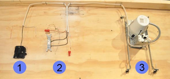
In the tabletop demonstration below, I have 14/2 wire starting at a circuit breaker (position 1) and going to a single-switch (position 2) that controls a bank of recessed lights (position 3). Pretend the breaker is housed within a breaker panel and the switch is in an appropriately sized box.
Pro-Tip: NEC 370-16 states that the volume of electrical boxes shall be sufficient for the number of conductors, devices, and cable clamps contained within the box. Nonmetallic boxes are marked with their cubic inch capacity. Use the following table to calculate necessary box size:
| Conductor Size | 14 gauge | 12 gauge |
|---|---|---|
| For each separate insulated wire | 2 cu in | 2.25 cu in |
| All ground wires (combined) | 2 cu in | 2.25 cu in |
| For each device (switch/receptacle) | 4 cu in | 4.5 cu in |
| All internal cable clamps (combined) | 2 cu in | 2.25 cu in |
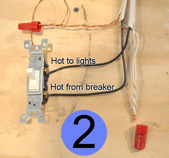
Here’s a closeup of position 2, and you can see that all the copper ground wires are spliced together with a pigtail going to the switch ground screw. The white, neutral wires are spliced and ready for a wire nut to be screwed in place. The black, hot wires are connected to the switch terminals.
Pro-Tip: On a single-switch, the hot wires and interchangeable so use a voltmeter to determine which hot wire is supplying power.
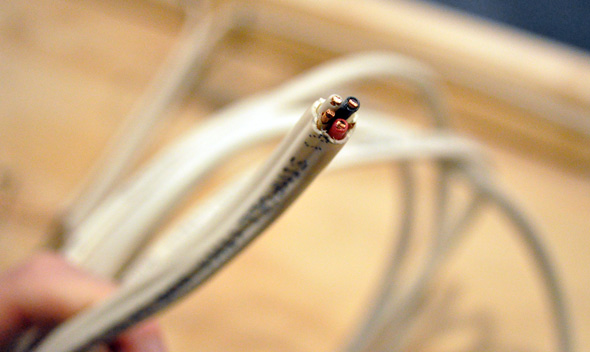
To install 3-way switches, I need to run 3-wire between the existing switch box and the new switch box. 3-wire (pictured below) bundles a hot, neutral, ground and traveler wire together.
In the picture below you can see that I’ve run a new 14/3 wire and connected two 3-way switches. While fishing the wires can be a laborious task, making the proper connections is often more confusing so lets take a closer look at the two new switches.
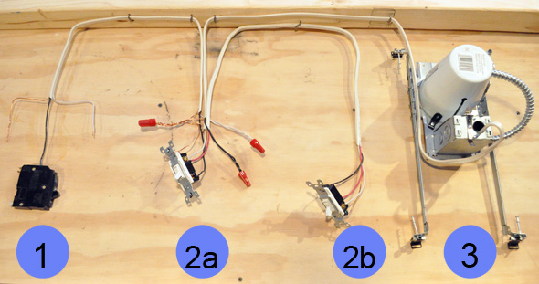
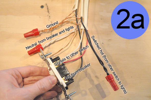
The first switch has three cables coming in- one from the breaker, one going to the lights, and one going to the second switch.
- All the ground wires are spliced together and pigtailed to the switch
- Like before, the neutral wires from the breaker and lights are spliced together
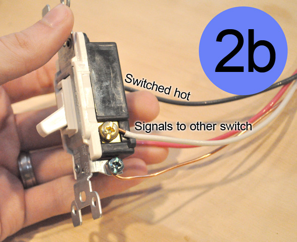
- The hot wire from the breaker is connected to the common terminal on the switch
- The white and red wires from the 3-wire cable are connected to the traveler terminals going to the second switch
- The switched-hot wires from the second switch and lights are spliced together
Pro-Tip: Identify the white wire as a switch leg by striping it with some electrical tape (not pictured).
The second switch is much simpler because there’s one 3-way cable coming into the box. On this switch, the white and red wires are connected to the traveler terminals, the switched-hot wire goes to the common terminal, and the copper wire to the ground screw.
A beautiful thing about the OPC workshop is that I can easily test this tabletop demonstration to make sure everything works. As expected, I can turn the light on and off from either switch.

Thanks Ethan! Just what I was hoping for. FYI the wireless add on switch seemed like a good solution, but there were some problems with it, namely that for some reason it requires at least one incandescent bulb in the circuit, which they don’t sell anymore. This article will solve my problem though!
Don’t be afraid to cut access holes in the drywall in every other stud bay. With a sufficiently large enough hole you can drill studs on either side of the hole. Then use two fish tapes and a strong rare earth magnet to get one tape through the whole run and then pull your wires. Be sure to mark the drywall cutouts so that they can be used as a perfect sized patch.
Good tutorial. i have to google this every time I want to wire a new 3-way switch.
or a 4 way.. you can just keep running more 3 conductor cable to another switch, the two ends are 3 way, the middle ones are 4 way.
and Ethan, please mark your white as hot with a little black tape!!
nevermind… you already said that. and I cant edit anymore, sorry.
but youre identifying it as hot (as in not common/effectively ground) not really the switch leg
There is one question I have, what about the NEC 2011 404.2 requirement that there is a neutral in each switchbox? I didn’t see anything exempting 3-way switches and there is now no neutral at your new 3-way switch.
actually, there COULD be, if you were to use a switch in that box that does need a neutral (lets say lutron maestro) then it wouldnt be using the switch lines as switch lines, but the switch line is just a data line to connect the switches, and then it would have hot and neutral, as well as ground, through that three conductor cable.
David, this is a good point and I’m not sure what the answer would be for extending an older circuit, especially since if the switch wire drops down from the light, there would be no neutral wire in the first box either.
I’m surprised the code doesn’t exempt one leg of a three way switch…. I guess the solution is that if you have a neutral wire in the first leg (as in this example), you run 14/4 Romex and carry the neutral to the new box, and then nut it off….
I should point out that the reason this happens is because we’re trying to run romex only from one switch box to the new switchbox. If you have the power come in from one side (i.e. switch 1), through switch 2, and then onto the light, you end up with a neutral at each box.
Great point David. I’ll investigate this further and report back.
I know this is a somewhat old post, but just came across this today so I thought I could add a relevant update: NEC 404.2(C) was updated in 2014 and again in 2017 to allow exemptions to the requirement. These exemptions appear to cover the way you’ve instructed here, provided that the entire room area is visible from both switch locations or if the installation was prior to 2020 (unless a rewiring can be accomplished without removing finishing materials).
https://iaeimagazine.org/magazine/features/do-we-need-a-grounded-conductor-at-that-switch-location-or-not/
I’m a little leery of working with electricity since I saw my brother get shocked real good when I was a kid. I don’t mind doing other projects but this sounds pretty simple to tackle and hopefully will save some time and money.
Yeah – as long as you really understand what’s going on, turn the power off, and check your work, electrical work is pretty safe.
Ahh, this brings back old memories of electronics classes. Very nice, and it’s always useful to lay things out on a table first too
The house I just moved in has this in a hallway and I need to replace one of them and this info is jkust in time.
this is perhaps the most helpful project thus far! combo this with your drywall patch tutorial and bingo, done deal!
Thank you soooo much! I finally understand how this works, and I set up my first working 3-way switch in the basement!
Thanks a lot for the detailed pictures.. exactly how i need it!
Let me just start by saying that my house was obviously not built by professionals… I have a light that has two switches already controlling it, but both have to be on for the light to work. I thought they both just needed a 3 way switch. When I went to replace the switches I found that there was only one black wire, along with one white and one ground. What would I need to do to make these work?
I now understand how to go from a switch leg to a three way switch.
Great Job
Thanks
I have an OLD stone house with a single pole switch to an overhead. I would like to drop a wire from the attic & install a 3 way switch, & I can replace the single with a 3 way & & I can run wire to the overhead, but I’m not sure I will be able to run new wire down to the single pole. Can I still make it 3 way? I’m not fussy about confused signals (I’ve lived in a lot of old houses where one switch controlled the power & the other turned it on & off.
Hi Folks
I’m trying to replace a single pole switch to a 3 way switch.
The new end only has a 3 wire, the existing single pole has been removed and a 3 wire switch it’s place, hot to common, red and black as travellers, the two remaining naturals are marretted together. Workes well when the replaced 3 way toggle is up but if down nothing. I’ve moved the travellers but with no luck
Huge help. With these step-by-step instructions it is way easier than the brain damage I was doing to figure it out on my own…!
Yup instructions worked perfectly. Builder didn’t add a switch at the top of the basement stairs to turn off the basement lights. Just finished this project by replacing the single pole switch at the bottom of the switch with two 3way switches, adding one at the top of the stairs. Followed the wiring diagram here exactly and it works. No more yelling at the kids to walk to the bottom of the basement stairs to turn out the lights. To my defense they were always able to out run the boogeyman coming up the stairs out of the dark basement 🙂
There are two ways to go about this if you are only able to route a Ga/3 cable from one switch to the other. In the first switch box you either splice and extend the line (breaker) or you splice and extend the load (light) to the second switch box. You’ve described the latter here. Neither way will allow for the neutral to be present in the second box unfortunately.