
Wiring an electrical outlet may seem intimidating until you’ve learned the right way to do it. This tabletop demonstration provides a detailed look at how to wire a typical, household outlet including properly splicing ground wires, stripping wires, making the appropriate connections and securing the outlet in the box.
Code and Electrical Permits
Permits: In some areas you are required to obtain a permit for electrical work that includes a new or extended circuit, and sometimes only licensed master electricians can obtain these permits. You can usually find where to file for permits via links on your county government’s or state government’s licensing and permits web page.
Code: Most jurisdictions follow some variation of the National Electric Code. You can get limited free access to the NEC via NFPA’s web site.
About This Demonstration
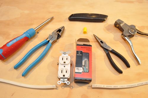
This tabletop demonstration illustrates one scenario for how an electrical receptacle is wired, and if you find wiring in your home that looks different, that doesn’t mean it was done wrong. Here are some details about this circuit that may differ from other circuits:
Type of Circuit
Most homes feature a combination of 15, 20 and 30 amp circuits, and the appropriate amperage depends on factors like location and power requirements. For instance, many household outlets are wired with 15 amp circuits. However, code requires that kitchen outlets be wired with 20 amp circuits to better meet the need for things such as microwaves. Today’s demonstration shows a 15 amp circuit, and it’s important that the circuit breaker, wiring and receptacle are all rated for at least 15 amps.
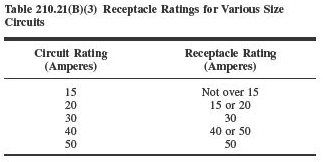
Tip: In some cases you can use a 15 amp receptacle on a 20 amp circuit, but not vice versa. Per table 210.21(b)(2) from the 2011 NEC:
Type of Wiring
As you might expect, different amp circuits require different gauge wiring, and this demonstration utilizes 14 gauge wiring. Also, the number of wires found within the sheathing may be different, and that is dependent on the application. For instance, 3-wire which contains a red, black, white and ground wire is used between a pair of switches that control the same bank of lights. Today’s walk-through uses 2-wire.
Tip: Heavier gauge wire is indicated by a lower number. For example, 12 gauge wire is thicker than 14 gauge wire.
Tip: The color of the sheathing usually indicates the gauge of wire. 14, 12 and 10 gauge wire is colored white, yellow and orange, respectively.
The Number of Cables
You’ll see two cables (bundles of wire) in this walk through, and that’s because this receptacle is in the middle of a circuit. If it had been at the end of the circuit, you’d only see one cable, and if the circuit had been further branched, you’d see more than two cables.
Wiring a 15 Amp Outlet
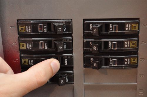
Step 1: Turn off the breaker
If the outlet you’re working on is already connected to the breaker panel, make sure to turn off the appropriate circuit breaker. I like to double-check the outlet with a voltmeter. If you don’t have one handy, just use a lamp (that you know works) to see if the outlet is powered or not.
Step 2: Strip Outer Sheathing
This demonstration assumes that the wire is already run to the box and in through the knock-outs.
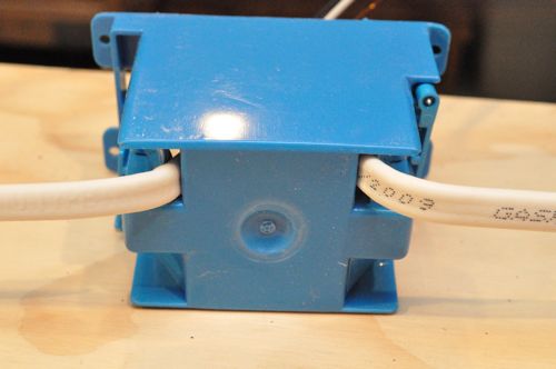
To remove the outer sheathing, run a utility knife along the length of wire, and cut the sheathing off just after the cable enters the box.
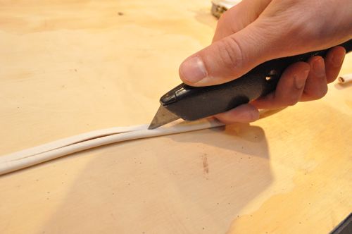
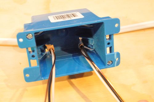
Step 3: Pigtail the Ground Wire
The outlet only has one ground wire connection so we need to securely splice the ground wires together along with a pigtail to make the connection. It’s a common mistake to think you can just wire nut everything together, and other online tutorials even instruct you to do just that! Here’s the right way to make the splice.

Start by bending one of the ground wires back on itself.
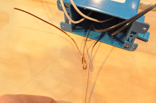
Cut the other ground wire to an equal length.
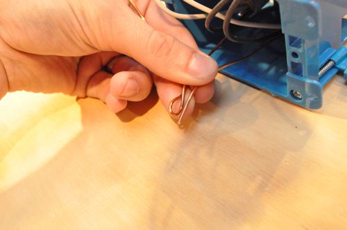
Use pliers to tightly twist the wires together.
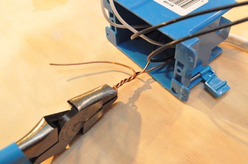
Next, cut the end off.
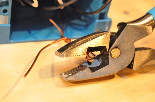
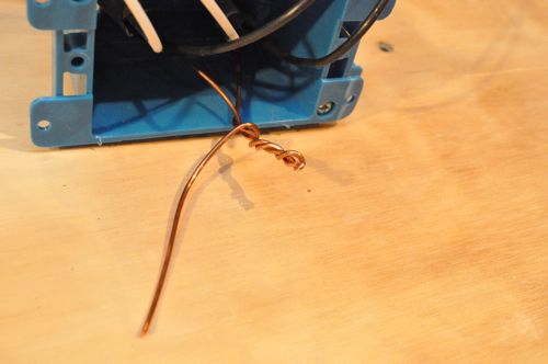
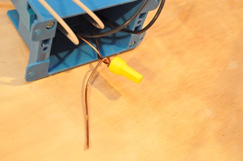
Lastly, secure a wire nut over the splice.
Tip: Wire nuts are available in several different sizes, and they are commonly color-coded to indicate capacity. Here’s a simplified guide for sizing wire nuts from The Home Depot.
Step 4: Connect the Neutral Wires
Pair up the neutral wires and trim them to an appropriate (equal) length.
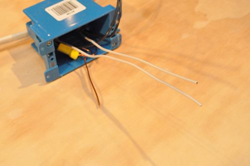
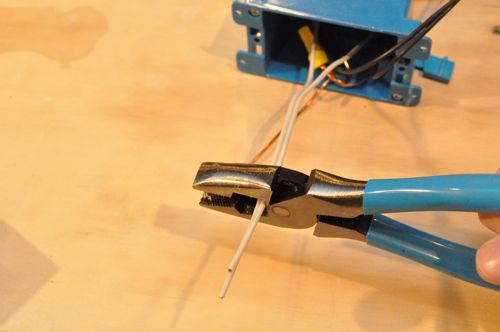
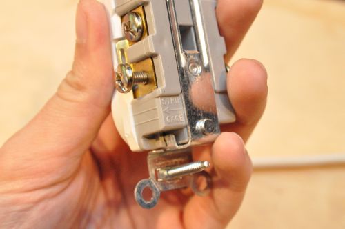
You can refer to the wire stripper gage on the outlet to determine how far back to strip the wire insulation. Be careful because you don’t want to expose too much wire.
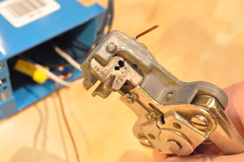
Grab your wire strippers and remove the insulation, keeping in mind that this is 14 ga. wire. Take care not to nick or damage the wire. If you do, cut the wires back and start over.
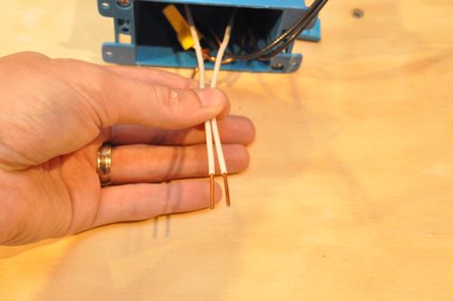
Using needle-nose pliers, twist a half-circle in the same direction that you’ll be turning the screw to secure the wire.
Note: Some outlets feature stab-in connectors (in addition to the screw connections) that allow you to push the hot and neutral wires straight into the backside of the outlet.
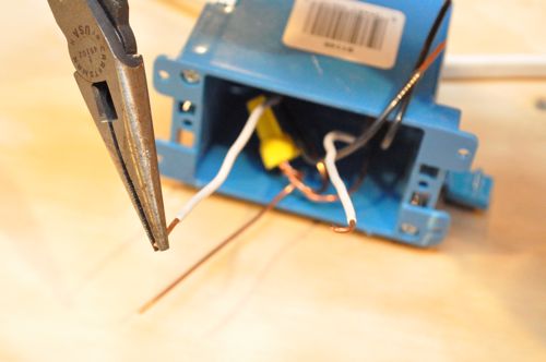
Loop the neutral wires around the silver screws in a clockwise rotation (the same direction the screws turn), and tighten down the screws.
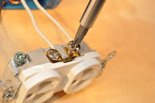
Step 5: Connect the Ground Wire
Make the same half-circle, and loop the ground pigtail wire around the green ground screw and tighten the screw down.
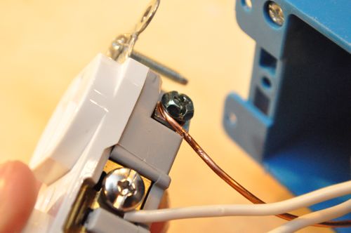
Step 6: Connect the Hot Wires
Repeat the process of trimming, stripping and securing the hot wires to the gold screws. Notice how there is no excess wire exposed.
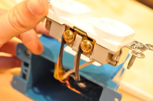
Step 7: Secure the Receptacle to the Box
The receptacle has two screws that hold it in the box. Fold all the wires into the box and tighten these screws. Keep the outlet centered in the box.
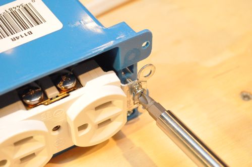
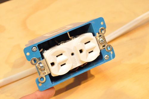
Step 8: Install Faceplate
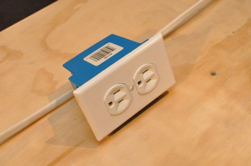
Lastly, the faceplate goes on with one flathead screw in the center, and you’re done.
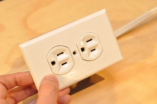


Nicely done. This will be a good go-to reference if/when I ever need to tackle this. Though I do have a friend who loves doing this kinda stuff and he works for beer. 😀
Hopefully the beer comes after the electrical work is done! 🙂 This seems pretty straightforward and about as easy as changing out a light fixture.
I’m going to have to use this guide. The electrical subcontractor that wired my house used very cheap outlets. Some of them have gotten where plugs fall out of them because the prongs are so loose inside the receptacles.
We have some of those, and they drive us crazy! I’m going to add this to our to-do list. Thanks for pointing that out William. 🙂
Some of the outlets in my house became very loose too. I don’t know the average life expectancy for outlets, but I’d imagine even well made outlets get to that point sooner or later. My house was built in ’85 so 27 years isn’t too bad IMO.
Could you add a section to this article to include wiring a switched outlet?
put a switch between the outlet and the breaker 🙂 or just follow the light article, and replace the lights with an outlet.
ok seriously, there are a few ways to do it, and it depends on where the power comes from, how many switched outlets you want, whether the switched outlets are fed by the same circuit or a different one, if you want a split outlet (one switched one always powered), etc.
Love the tutorial. You never know when you’ll need to add another outlet – my garage could use a couple more.
About the pliers to curl the wire, most good wire strippers will have a hole in the side that is placed so all you have to do is put the wire through the hole and twist.
Great comment Joe. I always forget about that hole (obviously) so I’m glad you pointed that out.
I dont think your crazy clampy strippers have such a hole, so I wouldnt expect you to use it much 🙂
If you’re using a metal box, you must also connect the ground wire to the ground screw on the box. There are several ways to do this, and one way is to loop one of the ground wires around the screw before having it come out of the box into the pigtail connection.
Also, some plastic boxes have a metal strip that connects a ground screw in the back to the screws where the receptacle itself attaches. Even though this is somewhat redundant, it should be connected for safety. In general, every piece of metal that is in (or is connected to something in) the same enclosure as hot wiring must be grounded.
Hi gregmac,
Thanks for the additional information, and you’re right on about ground connections. These days, you see fewer metal boxes, especially on newer construction. Even so, I appreciate your comment.
I’d also recommend picking up a GFCI tester like this one (http://www.amazon.com/Klein-Tools-RT200-Receptacle-Tester/dp/B005GYBFAE/ref=sr_1_9?ie=UTF8&qid=1336402615&sr=8-9). Cheap insurance to make sure you wired everything correctly. Plus it can be used to troubleshoot outlets that aren’t working or ensuring the power is off before you work