
Welcome to our latest Pro-Follow! Last week I spent time with local HVAC specialist Chuck Thompson from County Comfort as he and his crew changed out a heat pump. Chuck was called in because after about 15 years the old heat pump had failed. For this job they installed a new, 15 SEER, 5 ton Bryant heat pump.
Step 1: Disconnect the Old Indoor Unit
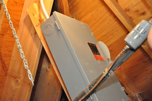
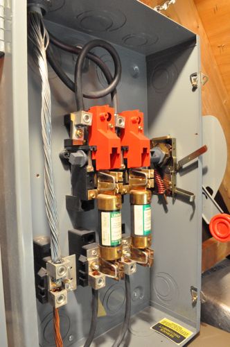
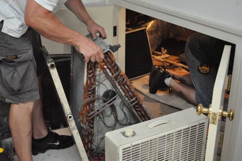
To begin, Chuck’s crew needed to remove the old system, and they started by turning off the breaker and disassembling the indoor unit to make it easier to remove.
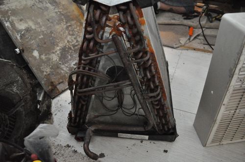
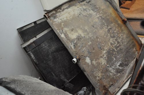
This is the old coil, and you can see signs of rust.
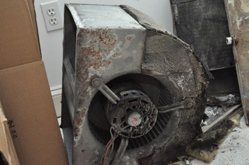
The old blower was in poor shape as well.
Here’s a look a the old pan.
Pro-Tip: Newer units often feature a fiberglass pan to eliminate the possibility of rust. However, fiberglass pans have a tendency to crack from being exposed to heat over time.
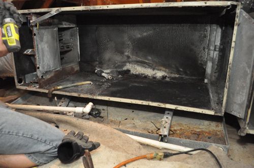
With the innards removed, the old housing was much easier to disconnect from the supply and return vents and the drain line.
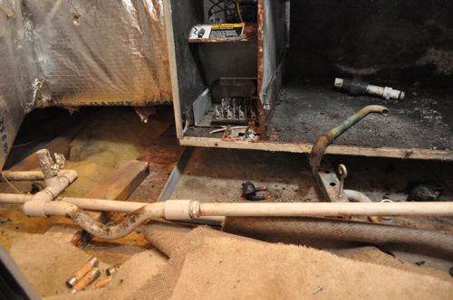
The guys were careful to salvage the coolant lines because they’ll be able to reuse them for the new system.
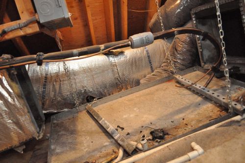
Step 2: Disconnect the Old Outdoor Unit
The outdoor unit was quickly removed by cutting the high-pressure and suction lines, disconnecting the power, and cutting the thermostat wires.
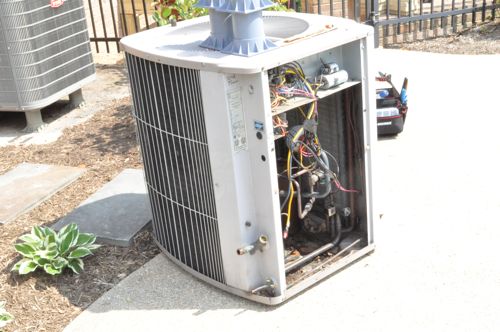
Step 3: Move New Outdoor Unit Into Place
Pro-Tip: Because of increased competition, many manufacturers are including 10 year warranties on standard parts for registered products.
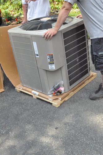
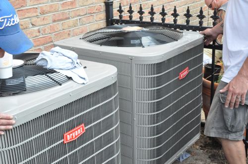
The outdoor unit is elevated off the ground with these four feet.
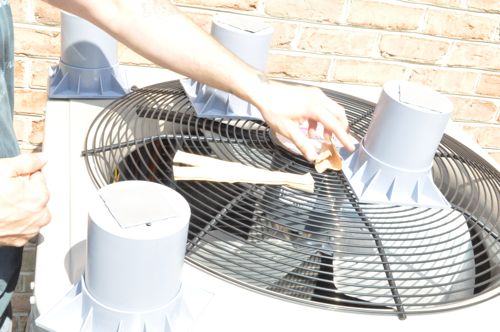
Step 4: Lay New Pan
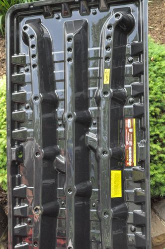
The previous indoor unit was suspended with chains, and the new unit will sit on this pan which features small mounts to reduce noise from vibrations and an integrated drain connection.
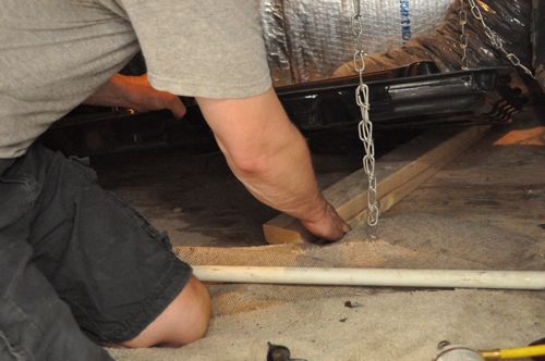
Chuck used 2×4’s to set the height so that the new indoor unit was in-line with the ductwork.
Step 5: Flush Coolant Lines
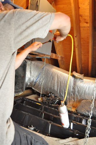
The newer system will use R410a coolant (rather than R-22), and Chuck used R-11 to flush the line sets
Step 6: Connect Thermostat Wiring
Back outside, the guys began connecting the outdoor unit, and they started with the thermostat wiring.
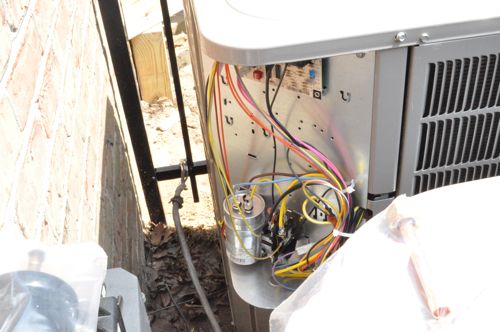
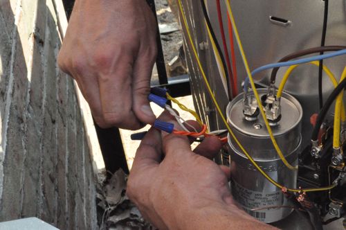
Step 7: Connect Power
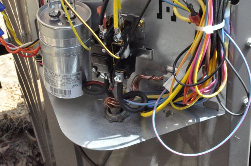
Next, they fed power through a connector and up through a knock-out.
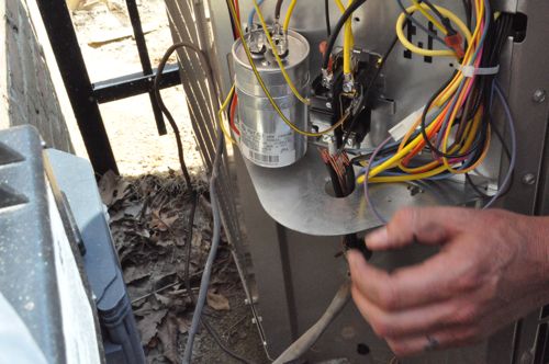
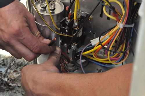
In the picture below you can see the two terminals side-by-side and the ground connection to the right.
Step 8: Install Filter Dryer and Braze High-Pressure Line
All HVAC coolant lines must be brazed, and Chuck’s team started by installing the filter dryer and the high-pressure line. The filter dryer removes contaminants and moisture.
First, the guys dry fit all the components for the high-pressure line.
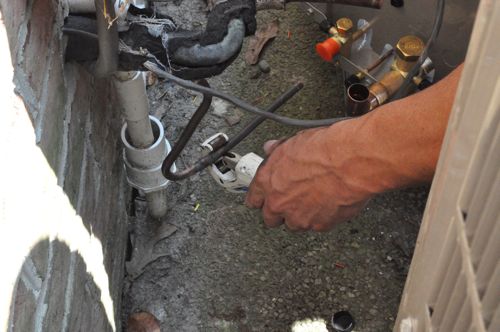
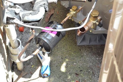
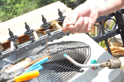
Next, they fired up the acetylene torch and prepared the brazing rod.
Pro-Tip: Using the torch to create a 90° bend in the brazing rod makes it easier to maneuver the rod into place.
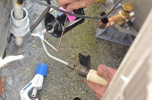
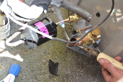
Step 9: Braze Suction Line
After the high-pressure line, Chuck’s crew brazed the suction line.
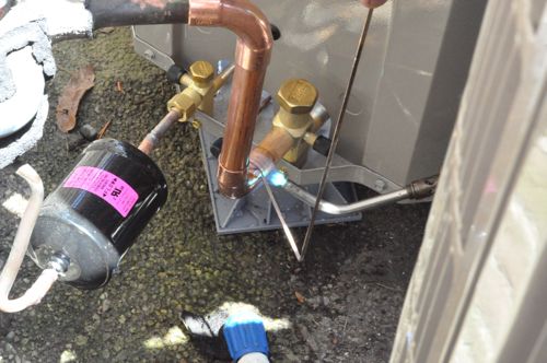
Step 10: Size New Indoor Unit
Back inside, Chuck team was measuring the new unit for size and working to ensure the supply and return ductwork would connect properly.
Pro-Tip: Newer units obtain a higher efficiency rating by increasing the number of coils. This means newer units are usually bigger and may not fit in the same location as the old unit.

They ended up needing to trim some of the ductwork, and the picture below some a piece of the pre-insulated ductwork found throughout the home.
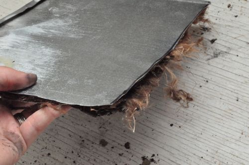
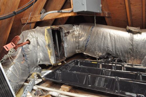
Step 11: Install New Indoor Unit
Just like removing the old unit, they removed some components to make it easier to move into place. The picture below shows the new unit butting against the return vent, and you can barely see the piece of sheet metal fitted along the top to narrow the opening to size.
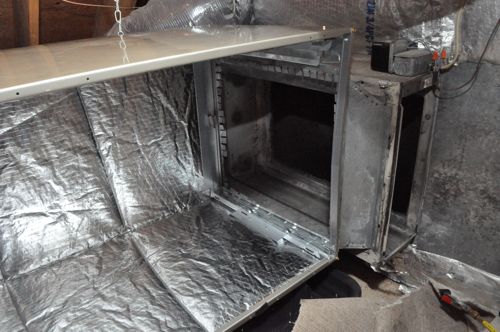
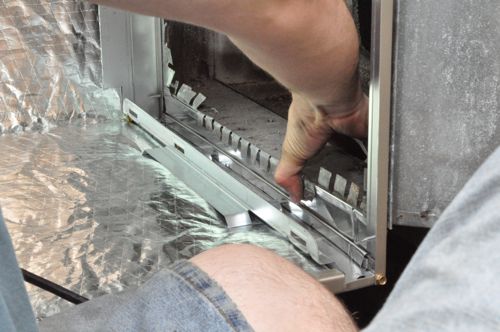
The indoor coils are designed to be installed upright or sideways, and you can see the two different pans for each configuration. The air filter fits into that narrow slot on the right just after the air return.
Pro-Tip: Manufacturers pressurize the coils with Nitrogen to verify there are no leaks, and when you remove the plugs, you can hear the Nitrogen exiting the system.
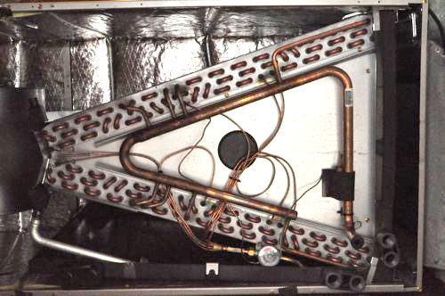
Next to the coil is the blower that forces air through the supply ductwork.

Step 12: Braze High-Pressure and Suction Lines
At this point, Chuck’s crew used a hand-held, pipe bender to carefully bend the copper lines into place.
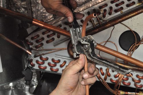
Next, they brazed the high-pressure and suction lines, and installed grommets (after the pipes cooled).
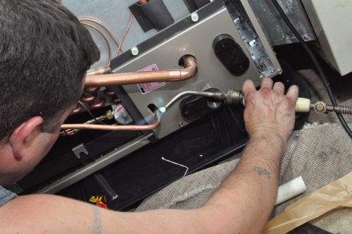
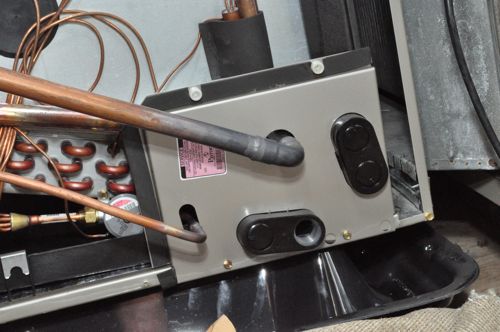
Step 13: Evacuate Coolant Lines
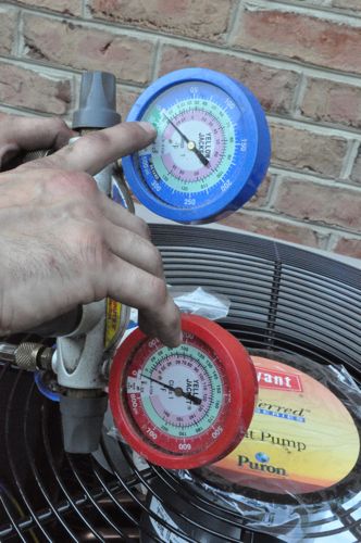
Back outside, the guys setup a vacuum pump to evacuate the line set.
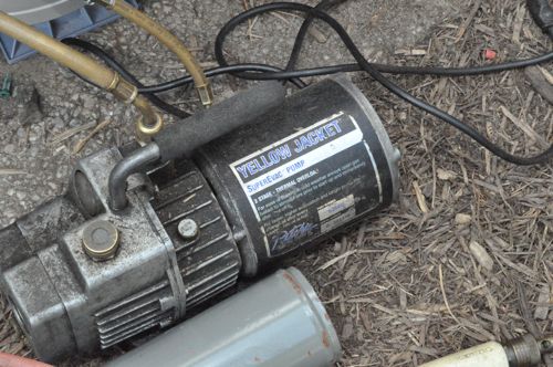
They usually let the pump run for at least 15 minutes and target about -30 psi on the suction line. After running the pump, they let the gauges sit to ensure no pinhole leaks are present. After that, they charge the line set with freon according to the manufacturers guidelines.
Pro-Talk: R410A freon is sold under the trademarked name Puron.
Step 14: Connect Drain and Emergency Shut-Off
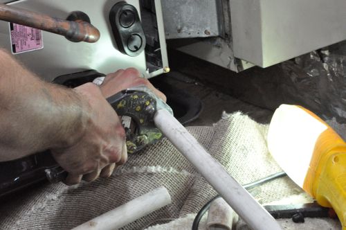
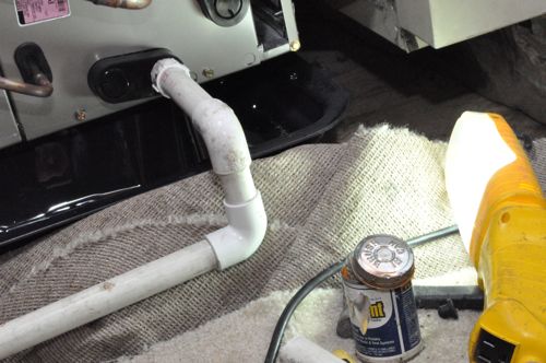
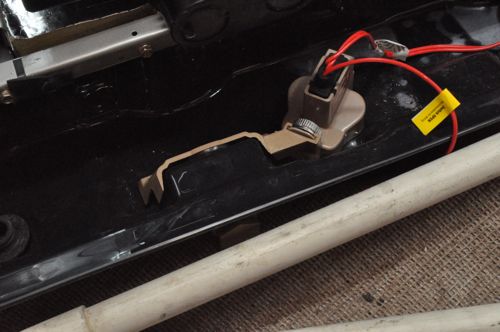
Next up, Chuck’s team made the PVC connections for the drain line and they installed the emergency shut-off mechanism on the pan.
Step 15: Connect Power
The guys reused the old wiring to connect power to the unit, and unfortunately, I don’t have good pictures of this step.
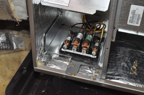
Finished
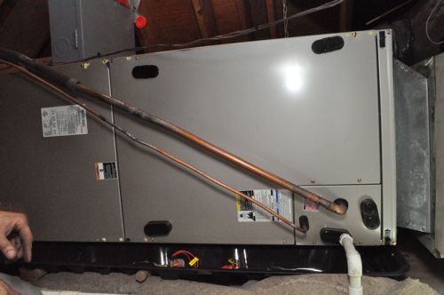
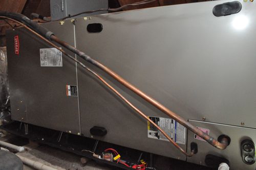
With all the final connections made, Chucks team turns on the new system and checks to make sure the air temperature difference is within range. Lastly, they use Rubatex to insulate the suction line and aluminum tape to cover any joints (not pictured).


Interesting Follow, but I dont think any of us are going to go and replace a whole HVAC system on our own (we probably cant even get the parts 🙁 ). but what about stuff we might be able to do on our own.. is there anything? The emergency shutoff? What about the pressure in the lines, is that something a motivated homeowner should be able to tackle?
You’re right that this is beyond homeowners and DIYers, mostly because of costly equipment. The bulk of what a homeowner can do is covered in that recent post about diagnosing a problematic HVAC unit. Hopefully, this Pro-Follow sheds some light on the process, and helps everyone stay informed.
Yep its so hard to get parts for AC units our relay got fried in a power serge. So the AC unit was due for repair. I asked my father to fix it for me he tested the unit and told me the relay was broken. My father was hard pressed to convince one of these businesses to sell him the part! They just want to charge u up the.. u know what to replace it. I think it was about $20 CDN for the part and was fixed in a matter of 30min by my father. In the past he even had to convince one company to sell him the gauges to check the Freon levels in his old Keep Rite AC that ended up being replaced due to a leak that could never be fixed. You need to have a license to buy the parts here and well we found someone who was willing to sell them back to us. Its not for the average person but my father has experience in many fields. So I wouldn’t suggest anyone else do it.
That’s weird to me that you can’t even buy parts. The appliance part supply house down the street sells to pros and joes alike. Joes don’t get the discount that pros do but then again, homeowners may only buy one part a year. I replaced my own relay with one from there. $20 and 10 min time. It took longer to research the fix online than it did to actually do it.
As MissFixIt has stated, as a homeowner it is almost impossible to purchase HVAC parts. Of the 4 suppliers local to me, none of them will even sell simple parts (like contactors or capacitors, mentioned in the earlier troubleshooting article) to a non-licensed HVAC technician. At least two of these are because they are not located in a region zoned retail – like an industrial park (or so they claim).
I have an electric heat pump pool heater, which is essentially an air conditioner in reverse (compresses heat from ambient air and exchanges it with cooler pool water). It has a rather dead-simple schematic/control system. I’ve had to replace the contactor, the start capacitor, a restart timer, and a corroded terminal based on rather simple troubleshooting (seems like one component per year – keeps life interesting). I’ve also had to go online to purchase most of the parts.
I take issue with Joe’s statement questioning the value of a non-DIY pro follow. There is plenty of value in them. First off, it explains the high cost of materials, labor, and specialized equipment when you see all that is involved. Second, you really get to the essence of what to expect when a pro tackles your job. Third, it gives you just enough information to enable you to ask the pros reasonable questions on how/why they do things and what types of materials and techniques they will use at the time of the bid to help weed out folks or understand why one bid is a bit more than the others. Finally, it can help you understand some of the proper techniques so if you see something that does not look right, you can stop them and ask questions.
In this particular follow, there are a few details that I’d like to add or ask about.
One is the TXV sensing bulb location – my understanding is that it should be mounted, via a copper strap with brass screws to the suction line on a horizontal run (best) or vertical line (ok) outside the plenum (then insulated). The line shown here was installed at a slant, making proper placement difficult. The last picture in the follow was prior to the final insulation, so it may have been added later. I can provide links to discussions on this topic.
Secondly, the follow states that brazing is done. This is important to distinguish from soldering – heck an entire article can be written on proper brazing techniques. If at all possible use a single run of tubing to minimize joints. My 9 year old compressor burned up, and as such the line set (tubing) needed to be replaced (worthy of mention is the line set replacement requirement -or several fill/purge cycles and extra filter- when replacing a burned out compressor). When pulling the old lines, the original install had elbows soldered (not brazed) at all corners. Strangely, the connections at the compressor and evaporator were properly brazed. The new line set was done as a single run, with the installer using a hand bender to form it the entire way, thus only requiring 4 joints. My installer states that the resin from the soldered elbows may have contributed to an early burn out.
Third, I’d suggest going through the exact tests in the follow that should be done by an installer before certifying the installation is A-OK. I’d recommend that the homeowner request to be present for these tests and document what tests were performed and what those values were for use during subsequent servicing or in case of later issues. I’ve heard horror stories of a bad install of a heat pump causing the emergency heat coils to run with every heat cycle, causing rather explosive jumps in the electric bill. Obviously, this was a check not made and the homeowner had to foot the rather outrageous bill. The extra 10-15 minutes of the installers time to assist you with documenting them is insurance for them as much as it is for you. As a hint, using an infrared (or any other non-contact thermometer) is NOT the right way to do these tests. That said, my home inspector when I was buying the place did a quick test with one and that got me a free new reversing valve and filter (ultimately it lasted 4 more years after that service).
Finally, I’d like to see the addition of upkeep/preventative maintenance/”visually check this after a good downpour” type of advice to the end of some of these follows. This one in particular can benefit from a ‘check and clean the coils’ and yearly PM visit to repeat the tests.
Whether an average joe can or cannot get the parts, I still think it’s a well written, informatve post.
dang, it wasn’t logged in! There’s something wrong with the cookies expiring or something.
I love looking at the pictures of the pro-follows! I have a heat pump system that was installed when the house was built in 1986, yes 26 years old, so it’s just a matter of time before this job comes up for me. I see that some of your pictures show the need for periodic cleaning and maintenance. Some questions. When the HVAC guy wants to add a new starting capacitor where none existed before, is it a worthwhile purchase? Why is it that no one sells a set of pressure-temperature-voltage-flow gages that can be permanently installed in these systems to allow us to monitor their performance? And is it really worthwhile to reuse the high pressure lines – microscopic corrosion is not an issue?
While I agree with the other posters that this is too much for a DIY homeowner, I enjoyed the article. It was a good example of when I should not try to do the repair myself and call a professional. I have a bad habit (and I’m sure others do too) of never wanting to hire someone when I think I can do the repair myself. Between the lack of proper tools and knowledge, replacing a heat pump like this is clearly something I would not want to take on.
Nice follow, Ethan. Series for removal/ replacement were well documented. Keep up the good work!
Do you use purple primer on the PVC connections? I have had good luck with the stuff, but from the pics it only looks like you used cement. Or maybe you are just better at hiding your work than I am. There always seems to be a purple seam where the cement oozes out… advice? Is purple primer not necessary here?
They didn’t use any primer on the PVC (and I assume it was not necessary).
By far, one of the most informative and highest detailed write-ups about heat pump installation! Kudos to you guys for the great article.
As stated before, this is definitely not a diy project. A few questions and concerns I have after looking at the pictures. When brazing the joints, did the installers purge the line with nitrogen? See how the one joint was completely black after brazing…that happens on the inside of that joint too if oxygen is present (it’s why we purge with nitrogen while brazing) and that oxidization can come off and clog the filter/dryers. Also, did they wrap the valves with wet rags while brazing? Those valves (especially the schraeder core valves) can be damaged and begin to leak if not protected. Also, was the system “flat” meaning all the R-22 had leaked out and made it unnecessary to do a reclaim of that refrigeration or did they just cut the lines and blast the r-22 into the atmosphere..in which case the EPA will issue a $10000 fine or higher.