Editors Note: Today we’re featuring a guest contribution by Joe, one of our regular readers.
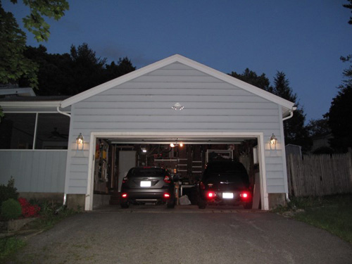
Originally, our house had landscape lighting and a sconce next to the front door, and the garage lacked any decorative lighting. I recently replaced the fixture next to the front door, and it looks much better. Unfortunately, we rarely use that door so the light isn’t used too much. We like having the landscape lights on at night (when we remember to turn them on and off) so we decided to install a timer and LED bulbs (to keep energy usage down).
I was really pleased with the timer, and I felt the garage could use some sconces flanking the garage door. Rather than install another time, I opted to use the same timer as the landscape lights.
I wont address every single aspect of the project, because they have already been covered here on OPC. I started with a new circuit coming from the sub panel in my garage. Everything related to wiring a new circuit can be found in this article Ethan wrote.
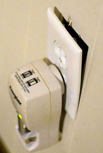
The timer I used is the Honeywell econoswitch, it automatically adjusts for sunrise and sunset times, as well as daylight savings, etc. You just input your location (in the form of latitude and longitude) and it takes care of the rest (obviously you need to set the time and your desired program). It also has a manual override.
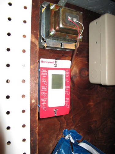
I wired this switch to an outlet, to plug in the landscape lighting transformer, and from that outlet I wired up the sconces. I had to have a direct run from the outlet to each sconce because the boxes I used are basically pancake boxes, and should really only have a single wire coming into them.
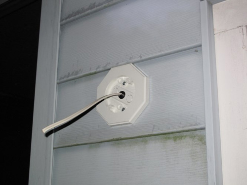
The boxes I used to mount the lights are really nice. Instead of having to modify the siding to fit the box you can just put the box OVER the siding, and (if you have normal siding) it will just match right up to it without any gap. It also has an integrated electrical box so the only penetration you need in the wall is for a single piece of wire. The boxes are made by Arlington, and have many styles for different types of siding. I chose the flat one because my siding has a very large lap (7/8″?) and very tall “boards”. The fit isn’t perfect, but its good enough.
I decided to center the sconces on the short wall on either side of the garage door, so I measured the wall for where I needed to drill for the wire based on where the knockout on the box was. If I had to do this again I would NOT have used the center knockout. I would have used one of the offsets. The center knockout put the wires right behind the mounting bar for the fixture, and put a screw right near the wire, making it more difficult to wire.
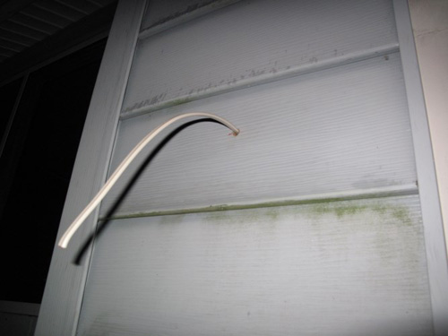
I pulled the wire through the wall and caulked around it, then I put the cable clamp in the knockout and pulled the cable into the box and mounted the box to the wall using the provided hardware. My house has plywood sheathing so I didn’t have to worry about mounting it on a stud.
I stripped the jacket off the wire and attached the mounting bracket for the light, then I had to wire up the fixture. I found that if I temporary mounted the fixture incorrectly, I could leave the wiring exposed and make my connections without having to hold the fixture myself.
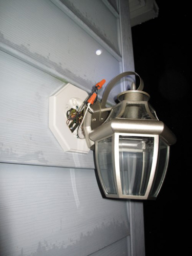
You can also see how that mounting bracket for the fixture is right over the cable coming into the box.
After making the connection I mounted the fixture properly and caulked around the top of it, leaving the bottom open to let any water out. the only thing left to do was plug in the landscape lights and put bulbs in the sconces.

The bulbs I used are LED bulbs that actually look GOOD exposed in clear fixtures, they have a glass globe and grey base, and a plastic light diffuser in the middle of the bulb. They’re not that bright, but I only wanted them as an accent light, so its perfect (they claim to be equivalent to a 25w bulb).

After turning everything on and programming the timer, all that I had to do was admire my work (oh, and that cleanup stuff).
Editors Note: Today we’re featuring a guest contribution by Jeff from Tool Box Buzz.
My wife and I had our first kid 3 months ago and since then we’ve been working room by room doing some minor baby proofing. In a couple of rooms there are outlets with stripped screws so that they are not secured to the junction box anymore. Instead of opening up the wall and replacing the box, it’s way easier and faster to drill and tap the holes up to the next larger size bolt. So in the interest of keeping our baby from using the outlet as a handle it was time to fix them.
Step 1
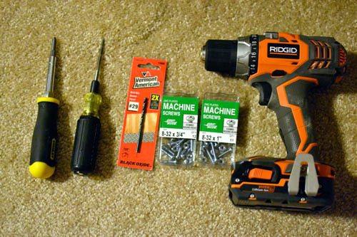
Gather your tools and turn off the power. From left to right: Screwdriver, Klein 6-1 tapping tool, #29 drill bit, various lengths of 8-32 machine bolts, cordless drill/driver. If tapping to a size other than 8-32 consult this chart for proper drill bit sizing.
Step 2
Confirm that the power really is off. Use a lamp if you don’t have a voltage detector.
Step 3
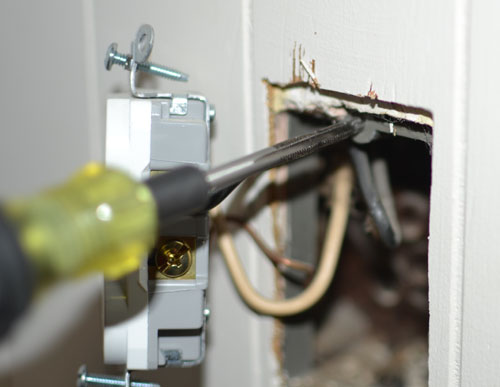
Unscrew outlet fasteners (leave wiring connected) and pull outlet to the side. Drill out the stripped junction box.
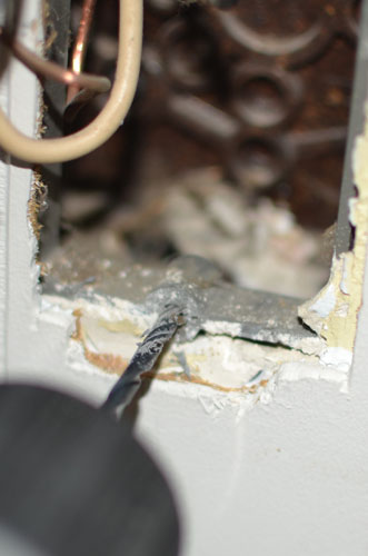
Step 4
Use the tapping tool and slowly turn it into the junction box. Be sure the wires are pulled to the side since the tap protrudes into the box. Also make sure to back the tap up every so often to clear the cutters. In my plastic boxes I backed off a half turn for every full turn forward.
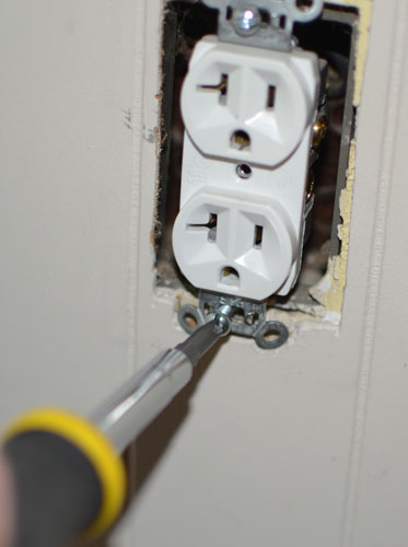
Step 5
Use the 8-32 bolts and reinstall your outlet taking care to fold the wires back into the box.
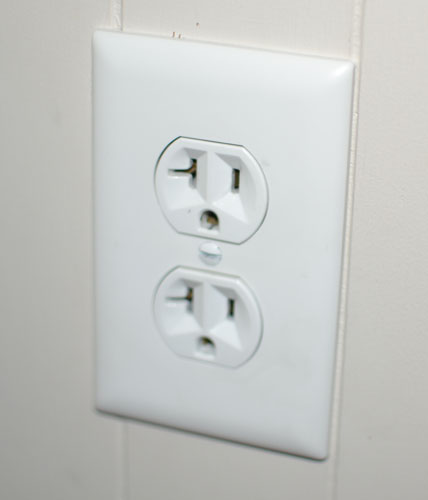
Step 6
Show your significant other your work so that they know how handy you are.
About This Tool
The Klein Tools 626 Cushion-Grip Six in One Tapping Tool can be found on Amazon for around $24 with free shipping. While you may only need 6-32 and 8-32 sizes for electrical outlets and fixtures I use the rest of the taps for other things especially the 1/4-20 tap. The handle is made in the USA, but taps are made in China.

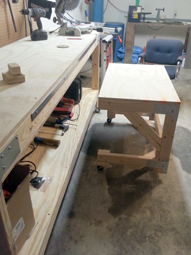
Today we’ve got a guest contribution from Ross, one of our regular readers. Ross built the OPC workbench, and then he followed it up with a terrific companion workbench of his own design.
When setting up my garage workshop after a recent move, I first made the heavy-duty workbench following the tutorial Ethan wrote. It’s already seen a fair bit of usage and I’m sure it will be used for many years to come. If you haven’t made one already, I recommend it!
If you follow the plans to make the heavy-duty workbench, you’ll find that after buying two 4×8′ plywood sheets, you’ll rip them down to four 2×8′ sheets and use three of them (two for the shelves and one for the torsion box on the top shelf). Wanting to further compliment the garage with another workbench, I set out to make a smaller workbench with the remaining 2×8′ sheet of plywood.
In addition, I also had the following goals:
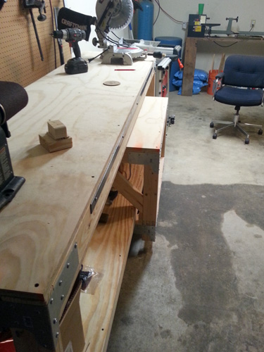
- To save space in the garage (two car garage that I park one car in), I wanted the bench to be able to fit underneath the main workbench.
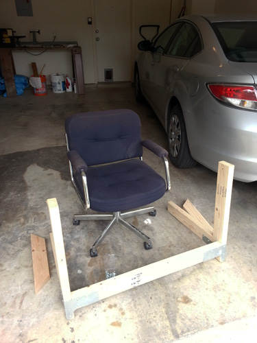
- Doing a fair bit of hand/detail projects, I wanted a lower table that I could fit over my shop chair for activities such as sanding or gluing.
- Additionally, I wanted to be able to wheel it around the shop along with my chair.
The bench I made has a final length of 40″ and is about 29″ high (I kept the width the same–24″). Specific dimensions may vary based on the height of the bottom shelf of your heavy-duty workbench as well as the desired height of the companion bench.
(Note: the design isn’t perfect and could certainly be improved upon. Share your ideas in the comments section below!)
Materials
- 3/4″ 2×8′ sheet of plywood
- 2x4s for the following components – (4) 8′ lengths should do it:
- (2) 37″ pieces for the back
- (4) 20-1/2″ pieces for sides
- (2) 26″ pieces for the back legs
- (4) 20″ pieces for the trusses (sides and bottom)
- (4) Simpson rigid tie connectors
- A box of #8 1-1/4″ screws
- (~10) 3-1/2″ screws for the trusses and front casters
- (~10) 1-1/2″ screws for attaching the plywood on top
- (4) non-locking casters – no particular weight rating, just not flimsy ones
- Liquid Nails (to improve strength of attachment joints)
Step 1 – Cut Lumber to Size
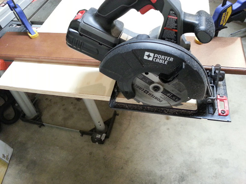
First, I cut the plywood sheet to the desired length. This was easily accomplished with a circular saw, and I clamped a spare board to act as a straight edge for the saw.
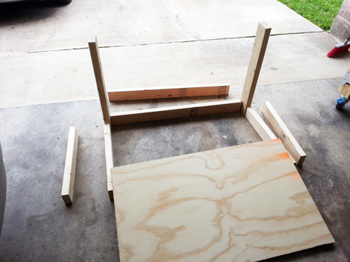
I cut the 2×4 sections to length, waiting on the trusses until after attaching the body frame.
After cutting the body sections to length, I laid out the pieces to make sure they looked about the size I wanted.
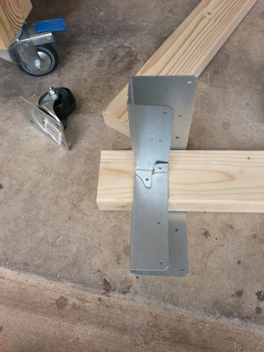
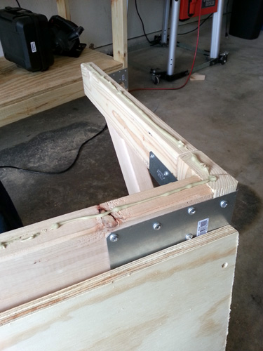
Step 2 – Attach Frame
When I was happy that the length and height would work, I went about attaching the tie connectors in the 4 corner joints. As a small tip, I’ve found it easiest to drill in the inside screw after attaching just a couple of screws on the outside. If you save the inside one for the end, it might be hard to line everything up.
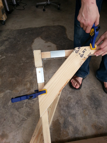
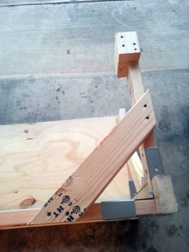
Step 3 – Cut and Attach Trusses
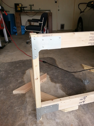
It was at this point that I realized that my initial plans for the bench didn’t take into account that the tie connectors extended below the joint (silly, I know). I had been planning on placing the casters right on the rear joint. I improvised a fix by adding some bottom trusses for the rear casters. I mitered two boards with 45° ends, approximately 20″ on the long side, and I attached these to the bottom of bench.
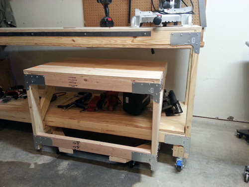
I used the 3″ screws for the trusses, and I drilled pilot holes to prevent any splitting. After attaching all the tie connectors and bottom trusses, here’s how it looked.
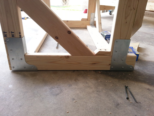
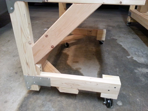
When planning the bench, I asked my engineer brother-in-law about the trusses and he said: “If you were to place a 300 lb load on the front edge of the bench you would create about 1000 lbs of internal force in each of the lower corner joints.” While I’m not planning to put that much weight on the bench, I wanted to be sure it would hold up. Without side trusses, the bench would be pretty weak so I cut some pieces about 20″ long.
Additionally, I screwed a small section of 2×4 in the very bottom corner joint. My thinking was that it would help support the downward force of the truss and further reinforce the joint.
Step 4 – Attach Top
At this point I attached the plywood top to the frame. I countersunk holes around the edges, laid down a bead of Liquid Nails, and screwed on the top.
Because of the added truss for the rear casters, I needed to attach a few blocks to the 2×4 side pieces for the front casters. I used Liquid Nails and some longer screws (pre-drilling the holes) to accomplish this. It isn’t an ideal solution, but it seems to work.
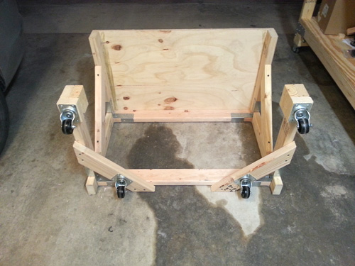
Step 5 – Attach Casters
Next, I attached the casters. For the rear ones, the further back they are positioned, the better the weight distribution will be.
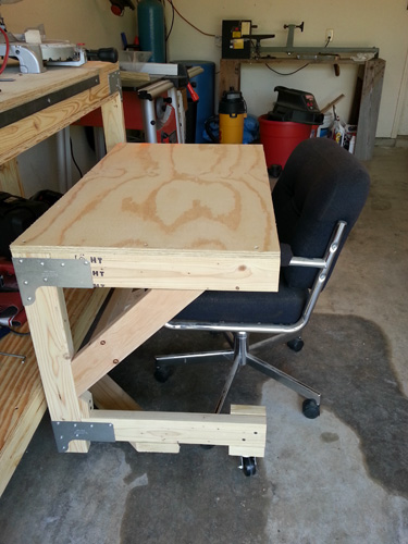
Step 6 – Try it out!
If you’re following along, hopefully all your measurements were correct and the bench fits well under your heavy-duty workbench!
What do you think? Would a companion bench work well for your workshop? How can the design be improved for rigidity (trusses, casters)?
Does your HVAC return duct make noises when the air handler starts and stops? Does your return duct “buckle” from the increased pressure when the supply is active? If so, your return duct may be slightly undersized for the rest of the system. This was the case for me after replacing a few components, and after the swap, I could hear the ductwork when the unit kicked on or off. One perk of hanging with contractors on Pro-Follows is that I can get their advice, and fortunately it’s easy to fix a noisy HVAC return duct.

Pro HVAC contractors I spoke with recommended cutting an additional opening in my return duct. Some time ago, we removed a whole-house humidifier that was mounted to the return and covered the opening with sheet metal. After removing the screws and cutting through the mastic, I exchanged the sheet metal for a return vent grille. After that, I waited for the air to cycle on / off, and I was pleased to find that the noise was gone.
It’s finally time to close the book on Fred & Kim’s basement remodel. I’ve been holding off on this recap because a few minor elements were on back-order and have just now been installed. In case you weren’t with us when we started this Pro-Follow, Fred and Kim hired Joe Bianco, professional contractor and president of SDG Home Solutions, to finish their basement. Joe has been involved in a number of Pro-Follows, tackling projects ranging from bathroom remodels to kitchen makeovers and more.
All of our Pro-Follows are created by showcasing the work of an expert contractor with years of experience in the field. Their knowledge and expertise is an unparalleled resource for completing home improvement projects the right way. If you enjoy our Pro-Follows, become an email or RSS subscriber and never miss an update!
This basement remodel included some very interesting aspects like checking the basement with a mold-sniffing dog, replacing an exterior door and flashing an already-built deck. It also provided the opportunity to create a very comprehensive guide for how to install a tile floor. I hope you’ll follow those links for the full articles.
Finishing the Basement
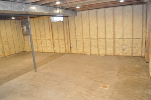
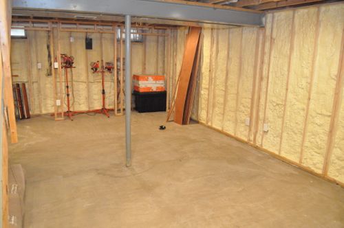
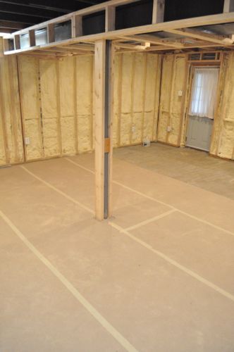
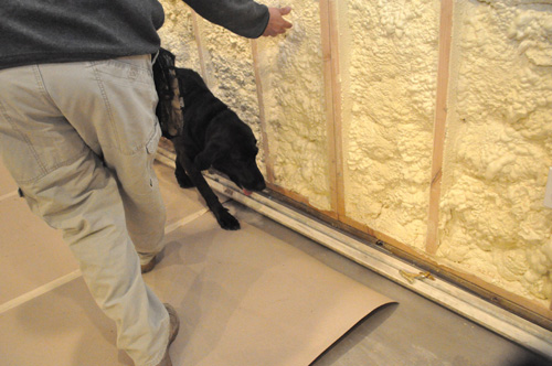
Fred did most of the framing and electric himself (with help from a licensed electrician). The basement is very well insulated with closed-cell foam, and you can learn more about that by watching our video about Installing Spray Foam Insulation. Here’s how everything looked when Joe began work:
Fred also installed over 1,000 sq. ft. of electric radiant heat and embedded the wires in self-leveling mortar (SLM) throughout the entire basement. When the radiant flooring is turned on, the basement gets nice and warm very quickly.
Joe brought in Russel from ETC Electric to tackle a short list of electrical odds-n-ends including some track lighting and junction boxes.
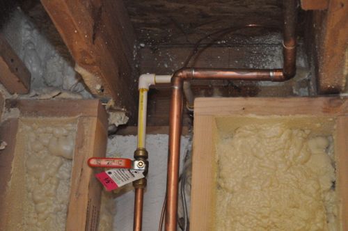
The plumbers from Drain Relief relocated a few valves, replaced some hose bibs and ran a new line for the refrigerator water supply.
The framers didn’t have too much rough framing to complete either. Joe had them frame around a bulkhead and stairs, frame in support poles, ensure drywall nailers in all the corners and frame around some plumbing.
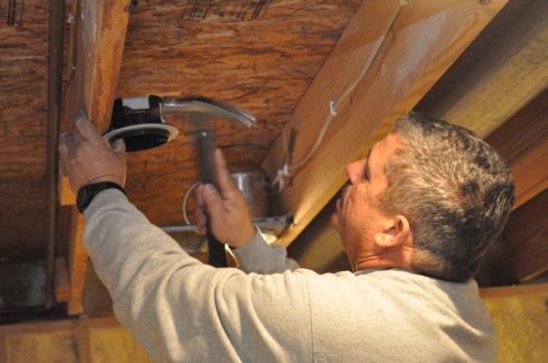
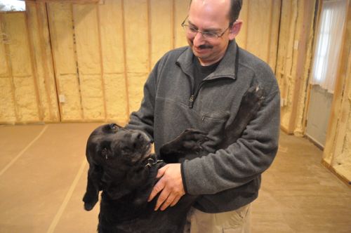
Soon after the framing was completed, Joe brought in Dave Marcelli from Mold Trackers, LLCÂ to determine if there was any mold in the basement. Fred and Kim were concerned about a leaky ledger board, and they wanted to address any mold before covering the walls with drywall. Fortunately, Dave (and Sam) didn’t find any mold problems.
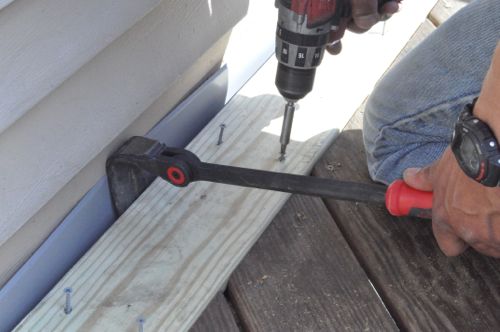
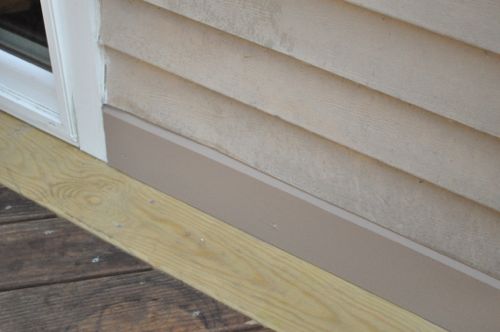
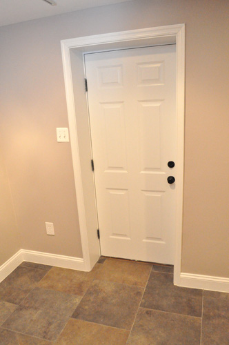
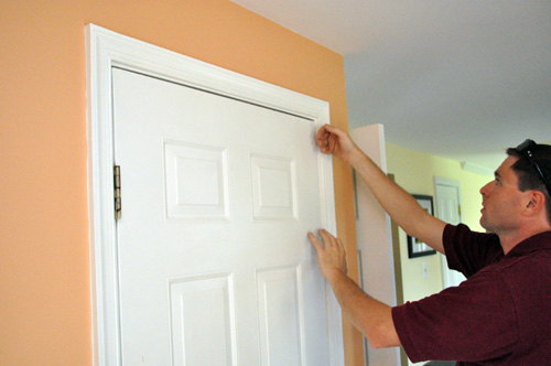
A deck ledger board should be flashed (waterproofed) when it is first installed so flashing an existing deck is no easy task. I thought Joe’s solution to flash and install a PVC “baseboard” was a good one.
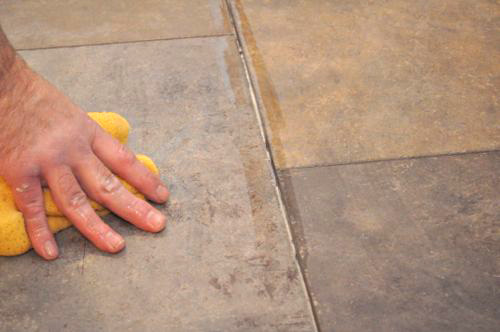
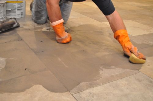
I think the best part of this Pro-Follow was partnering with Jim and Rich from Diamond Tile to show how they laid the tile floor. The guide I developed from working with Jim and Rich is very detailed and walks you through every step for successfully installing a tile floor. Bookmark that article if you’re ever planning on installing tile.
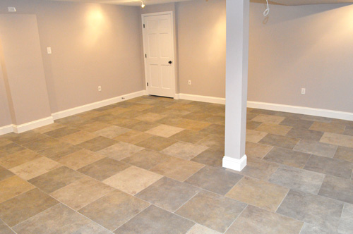
Finished
Here’s a look at the completed basement remodel. It looks really good, and Fred and Kim were very impressed with Joe’s attention to detail. I know they’re very ready to start using the space.
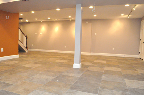
Those dangling wires are speaker wires for whenever Fred and Kim decide to setup a TV area, and that door in the background is actually the access to the electrical panel.
Fred and Kim love central american artwork, and the track lighting will enable them to better show it off.

The foosball table is already setup and ready to go.
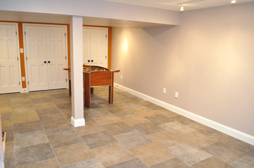
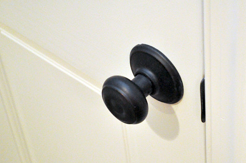
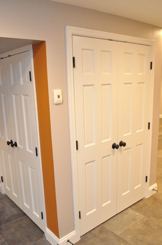
Previously the basement was used for storage, and Fred and Kim incorporated some closets to keep a little bit of that storage space.
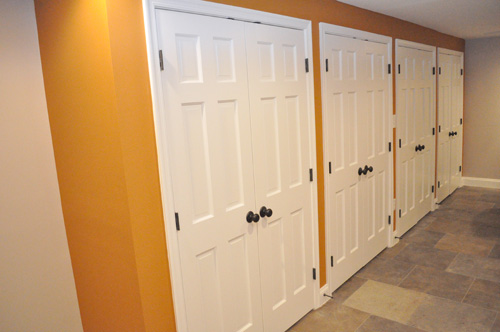
The HVAC unit and water heater are situated in the middle of the room and two sets of doors provides plenty of access.
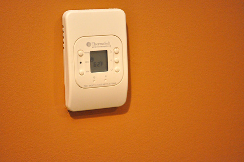
This is one of the thermostats for controlling the radiant flooring.
Here’s a look at the stairs. The rail and newel post were one of the last things to be installed.
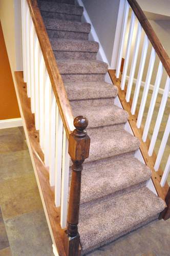
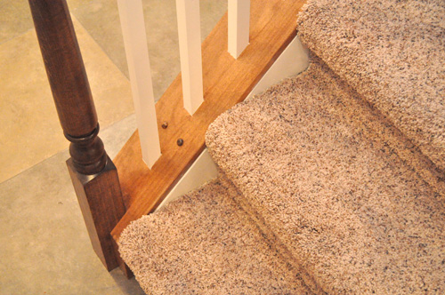
The stairs are the original stairs to the basement, but you wouldn’t recognize them with all the work that’s been done. The treads have been padded to meet height requirements and extended to create that slight overhang. Risers were added, and either side of the staircase was framed out to support the railing. Joe stained, painted and installed the railing himself.
I hope you’ve enjoyed this Pro-Follow series. I don’t have the next one lined up yet, but look for more to come this summer. Next week I’ll be out of town, and I have some excellent guest contributors lined up.
Today we’re featuring a guest contribution by Matt from the DIY Village on building a custom fire pit. If you don’t know Matt and Jacque, hop on over to their site. It’s chock full of awesome DIY articles!
When it comes to transforming a back yard, an outdoor fire pit rates high on everyone’s DIY to do list. When my wife, Jacque and I purchased our new home a few years ago, we were moving from a townhouse. One thing that always bugged me about living there was that we were restricted on what we could modify outside of the footprint of the house, as the yard itself was considered common property. So when we made the decision to move, one of the first things I thought of was how great it would feel to be able to decide for ourselves what our new backyard should look like. The first thing on my list was a custom fire pit.
We’re lucky to have an incredibly talented friend, Jesse Hoffman, who is a professional landscape designer. We coaxed him into stopping by and sharing his thoughts on what we had in mind. I had envisioned a circular stacked stone fire pit, but Jesse introduced an idea that involved a more unique shaped fire pit and landscaping around it. I think Jacque saw an opportunity to coach him into adding the landscaping as part of the project just to add more to the “Never Ending Honey-Do-List” (Of course she’d never admit to that). Jesse’s idea was to have a fire pit in the shape of an eye, have an area for seating in front of it and a mounded landscape bed surrounding the backside.
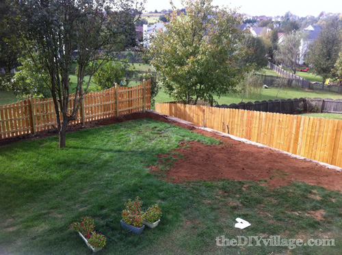
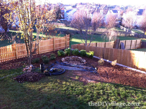
Here’s what we started off with…Basically just a blank canvas!
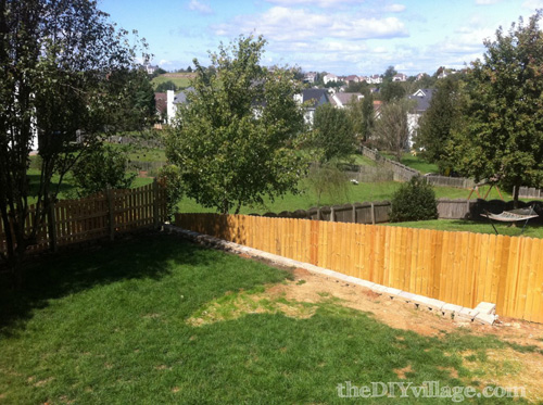
We had to bring in more fill dirt to level out the areas next to the retaining wall.
Next we laid out the design onto the ground with spray paint to give us a feel for where everything would be, plus it made it easier to know where and what to dig!
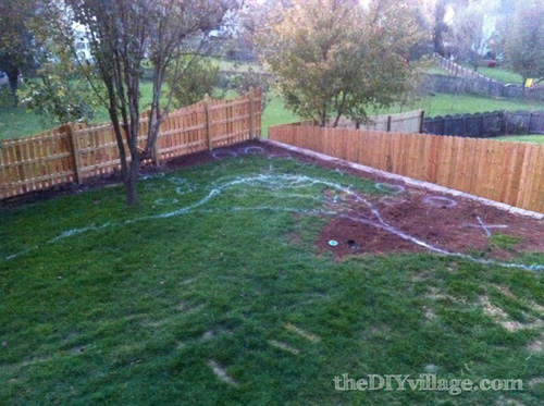
Then we brought more dirt in to build up the landscape beds. Altogether we hauled in an additional twelve cubic yards of fill dirt.
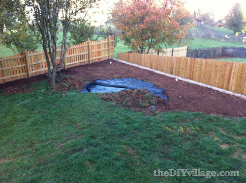
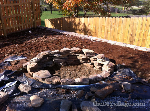
The next step in the installation was to dig out the actual shape of the fire pit. As you can see in the picture below, I created a drain channel within the patio area of the fire pit. I added this because our yard has a natural slope towards this corner and wanted any run off to be routed elsewhere. For the actual fire pit shape, I chose to dig down about eight inches which allowed me enough room to lay a base layer of gravel to allow any water to drain below the surface of the fire pit itself.
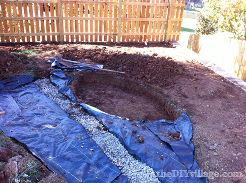
With the gravel in place we then began to stack the stones to around the perimeter of the fire pit. Truth be told, there wasn’t much skill involved in the stacking process, I just basically used stones that stacked nicely side by side and on top of each other. I could have used mortar to secure the stones in place, but with the height being so minimal and the higher stacked backside being built up against a mounded landscape bed, I felt that there was already plenty of stability.
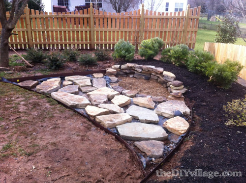
Now that our custom fire pit was practically complete, we brought in the shrubs to finish off the custom look. We were careful to choose a variety of plants that wouldn’t leave the yard feeling bare in the fall or the winter.
We placed flagstone pavers to make up the area where we plan to having seating and we placed metal bed edging to help border and define that space.
Lastly we added pea gravel as filler in between the flagstones and we added a few low voltage landscape lights to accent the area at night.
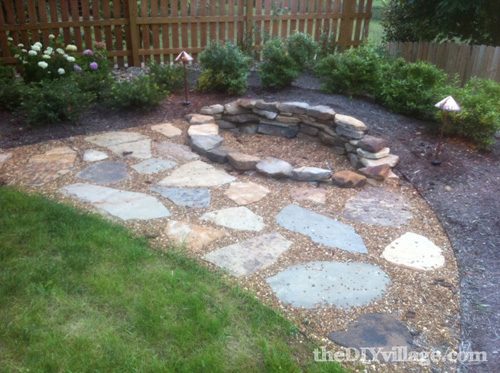

Every time we build a fire out back, I’m reminded how nice it is to have the freedom to choose how I want my yard to look. Having a custom fire pit really added a nice decorative touch to a previously sparse yard! If you’re looking for more outdoor project inspirations, we’d love for you to check out our DIY Paver Path!
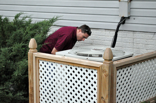
Recently a friend was having a professional home energy audit performed, and I asked to tag along. I was curious to learn what tools and techniques a professional uses to analyze the efficiency of a home. I also wanted to learn what actions an auditor would recommend. The audit was performed by James from Energy Services Group, a local business specializing in residential energy conservation since 1981.
If you live in central Maryland, Baltimore Gas & Electric (BGE) is probably your energy provider. The state of Maryland requires BGE (and other providers) to develop energy efficiency programs with the goal to reduce electric consumption by 15% by the year 2015. Examine your monthly bill next time and look for the EmPower Md. Charge. That fee funds the programs and enables BGE customers to take advantage of services like the Home Performance Energy Audit at a fraction of the cost. According to the BGE website, the Home Performance Energy Audit costs $100, and it’s a $400 value. Furthermore, a number of home improvements quality for rebates through the BGE Smart Energy Savers Program.
My friend’s home energy audit began with simple information gathering. James toured the house, examining the interior and exterior and noting the various appliances and utilities. He mapped out the house and measured the volume of each room. My friend also provided 12 months of utility bills.
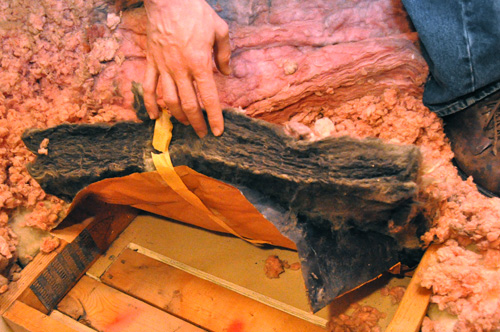
Home Energy Audit: The Attic
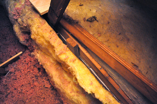
The attic and basement are where home energy auditors find the majority of problems, and James started in the attic. He quickly identified a section of fiberglass insulation that was all black. Homeowners commonly think the insulation has mold growing on it. However, that was not the case. The insulation was discolored from dirt as air continuously passed through it (much like a furnace filter). This was a great indicator of where air was infiltrating the house from the attic.
Pro-Tip: Attic fans are an active way to cycle air through an attic. James likes to recommend passive approaches like ensuring soffits and the ridge vent are clear because passive methods create fewer points of failure.
My friend’s attic had the right amount of insulation. Unfortunately, in a few places it wasn’t against the structure and therefore not actually insulating anything. James also suggested using weather-stripping and 6″ of rigid foam board to insulate the attic access panel.
Pro-Tip: If you’re planning on making the attic a living space or have a significant number of utilities running through the attic, consider a hot roof to incorporate the attic into the conditioned space.
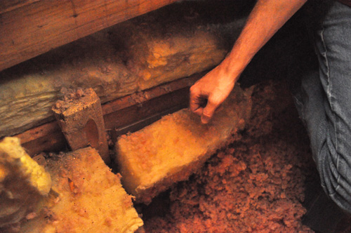
Home Energy Audit: The Basement
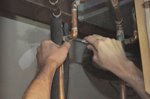
Next, James went to the basement, and he insulated the hot and cold water pipes.
Pro-Tip: The 2012 International Energy Conservation Code (IECC) section R403.3 requires a minimum of R-3 on piping carrying fluids above 105°F (41°C) or below 55°F (13°C). See the Related Content section for a link to the free, online IECC.
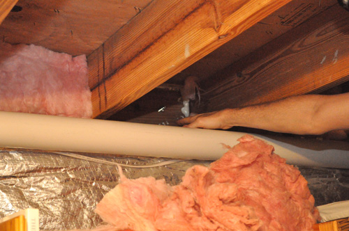
My friend had previously insulated a portion of his band boards, and James recommended finishing the job. James suggested cutting rigid foam board to fit against the band board and sealing the edges with Great Stuff.
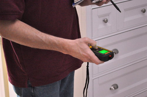
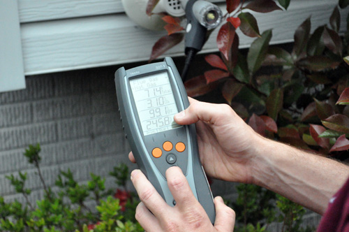
James checked the gas lines for any leaks, and he analyzed the ambient CO levels around the HVAC unit and gas range in the kitchen.
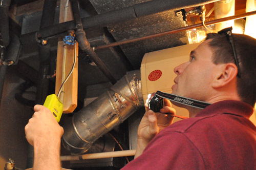
James also ran a Worst-Case Depressurization test to verify combustion safety. Basically, James was measuring the amount of negative pressure with all the exhaust fans (kitchen hood, bathroom vent fans, dryer, etc.) running to see if it was enough to create a backdraft.

James also analyzed the amount of carbon monoxide exhausted by the furnace. High levels of CO indicate poor combustion and low efficiency and vice versa.
Pro-Tip: James recommends a CO detector on every level of the house.
Home Energy Audit: Blower Door Test
Lastly, James performed a blower door test, and these are very helpful to determine air leakage.
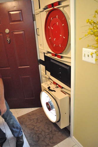
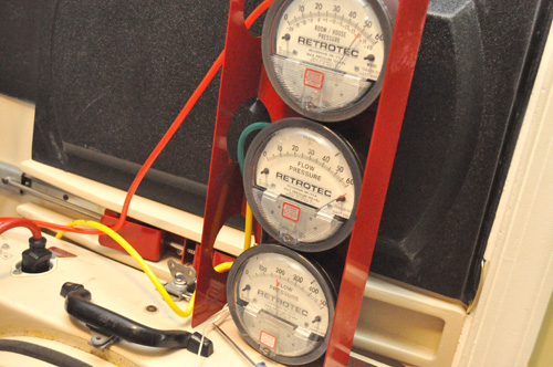
James setup all the equipment in the main entry door and used the fan to create a negative pressure.
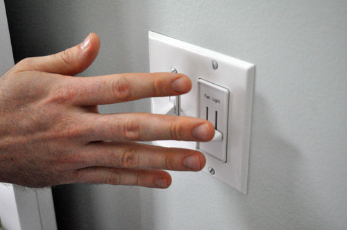
Next, we walked the house finding air leaks. The most common culprits included around switch and outlet boxes, ductwork junctions, attic access and doors. It was amazing how easy it was to feel the air coming through.
Pro-Tip:Â Rather than address air infiltration around electrical boxes, James suggests stopping it at the source by sealing the top plate of the wall framing.
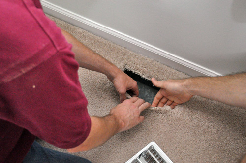
We could feel air moving at the junction between the ductwork and the floor (not through the ductwork), drawing unconditioned air from the space below.
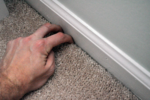
Much like the insulation in the attic, some carpets build up dirt adjacent to the wall from “filtering” the air as it moves though. I was surprised to find how leaky the wall was around the bottom plate.
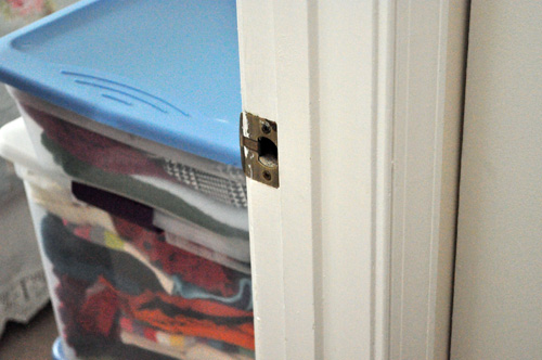
Another surprise was the amount of air moving through this door latch. Air must be traveling through the top plate, wall framing and out through the strike plate.
James paid special attention to the door leading to the garage because that’s often a source of VOC’s and other potentially harmful gases.
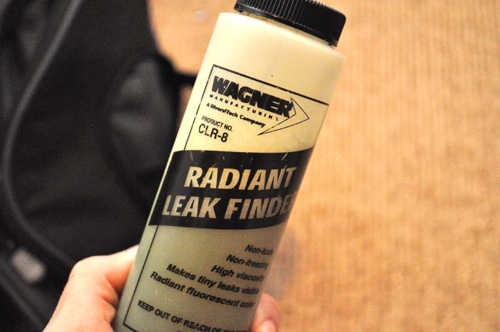
James performed some other miscellaneous tasks like installing CFL bulbs and faucet aerators. Normally James would examine the insulation with a thermal imager. Unfortunately, here in Maryland the outdoor and indoor temperature are about the same right now so he omitted that step. Altogether it was a very educational audit. It let my friend know exactly where air was entering the house and the best way to address the problems.
Update May, 2014: After a full year, our deck continues to look great and we are very happy with Rustoleum’s product. However, other users have had a poor experience with this product and that is reflected in many of the comments. It is important to note that people visiting who do leave a review are more likely to write a negative review than a positive one. This happens because people only look for reviews on sites like ours after they use a product when that product didn’t perform well. We have not taken the time to analyze all of the use cases, as this product was installed on our deck (and we only have one!). It could be that this product performs better on certain wood species than others, or with certain pre-treatments, or in certain climates. It may fail when being used over top of an existing stain, or over top of newer wood. Given the number of negative reviews below, and the amount of negative user reaction on Rustoleum’s Facebook page (www.facebook.com/rustoleum), we encourage you to tread cautiously before proceeding.
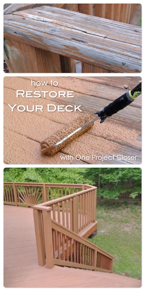
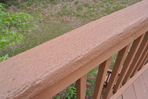
Early this year Jocie and I attended a Rust-Oleum media event. They shared information about several products, and the one that really piqued my interest was the Rust-Oleum Deck Restore. They described it as a thick coating that fills gouges and cracks and buries splinters. It also hides imperfections, and the textured surface is slip resistant. In short, Rust-Oleum Deck Restore sounded like the perfect product for my old, weathered deck.
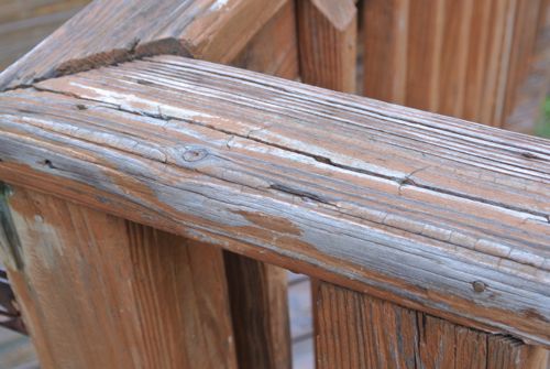
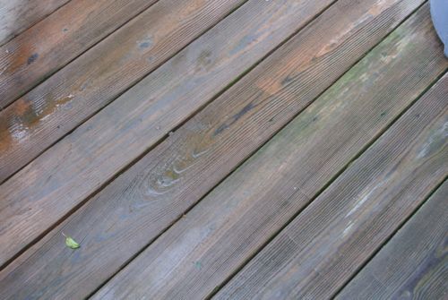
When Jocie and I purchased our home, the deck was already a bit neglected. It was bad enough that you’d easily get splinters, and subsequently we never spent too much time on the deck. If you know anything about decks, they require periodic cleaning and sealing to combat mother nature. Fred and Kim went through the process with their pine deck and used Behr Premium Deck Sealer. After witnessing their experience, I was convinced composite decking was the way to go. However, the cost for materials to re-board the deck was high enough for me to abandon the idea. Needless to say, I was excited about a low-cost alternative that would enable us to enjoy our deck again.
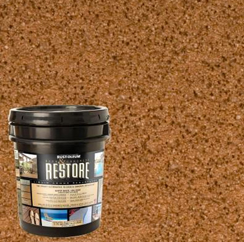
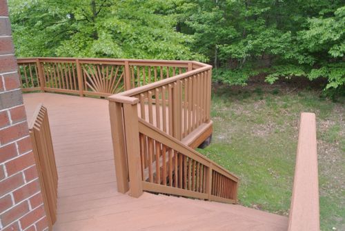
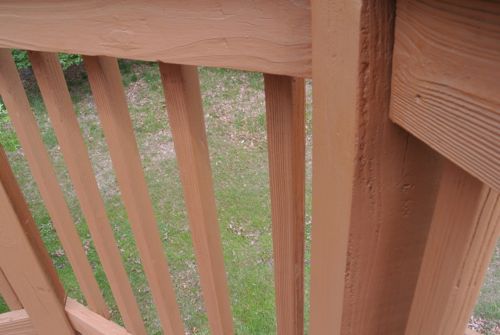
Rust-Oleum kindly provided enough Deck Restore to cover the horizontal surfaces of our deck and stairs. Deck Restore isn’t intended for vertical surfaces (like balusters) so they also provided a matching solid acrylic stain. Rust-Oleum offers a broad range of color choices, and we selected Saddle. I estimate all the materials cost approximately $450 (Deck Restore, stain, rollers, roller grids).
Preparing the Deck
To get the deck ready, we cleared it off and removed any embedded dirt. Around here the Oak flowers can be a real hassle, and we had to sweep the deck periodically.
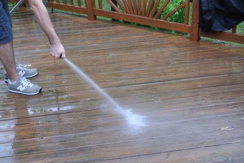
The deck needs to be dry before applying Deck Restore so we waited till the next day to resume.
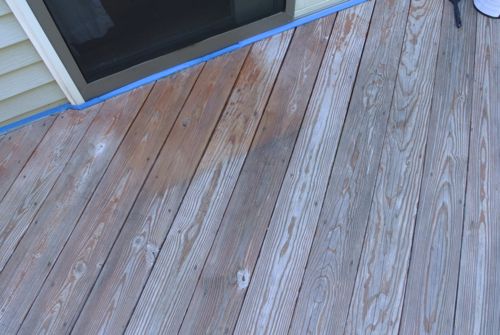
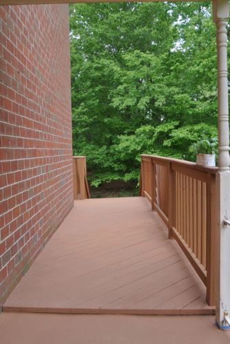
We taped off were the deck meets the house. We also covered the shed underneath the stairs and the HVAC unit underneath the deck.
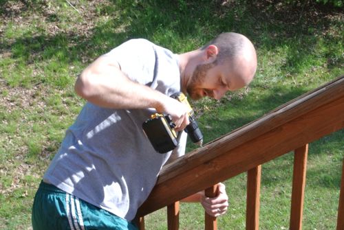
I went around with a hammer to pound in any nail-pops. I also removed various hardware like the gate latch and some plant hangers.
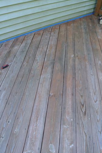
I put in a bunch of screws to further secure the railing and any boards that had a tendency to bounce.
Applying Rust-Oleum Deck Restore
Deck Restore is very thick, and we used a lot more product than I expected. Rust-Oleum states that a four gallon pail covers about 100 square feet with two coats. It’s applied with the Restore rollers which are a polyester honeycomb roller designed to help texture the surface of the deck boards.
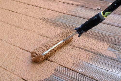
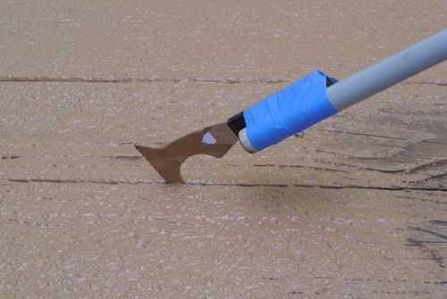
I rolled it on in the direction of the deck boards, and I was pleased to see it fill in so many cracks. I also rigged up a painters tool for edging the boards. More on that later though.
While the first coat dried, I went to work on the stairs.
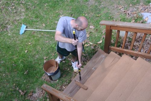
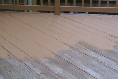
Four hours later I was back applying the second coat, making sure to fill in missed areas like the one pictured below.
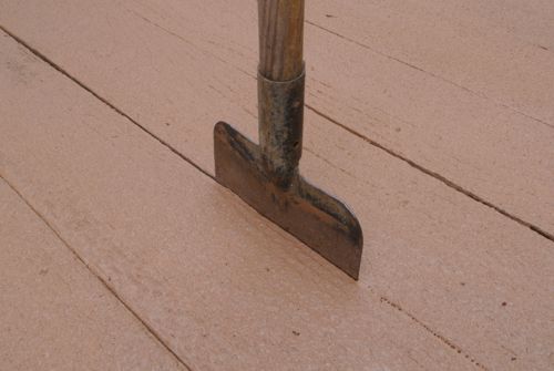
I found that letting the Deck Restore dry enough to walk on and using a garden hoe to cut the gap between boards worked really well. It resulted in nice, clean lines.
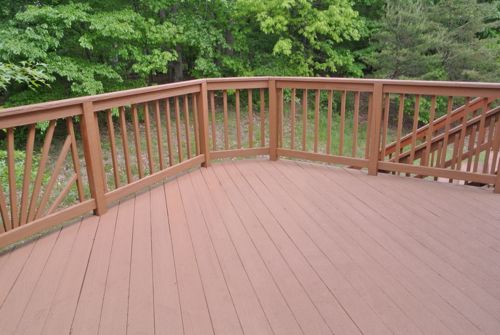
The Finished Product
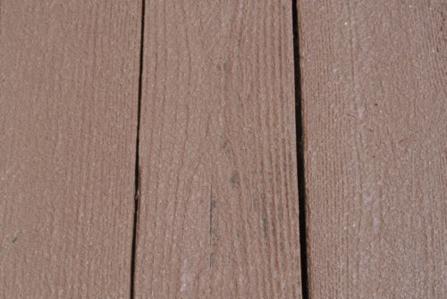
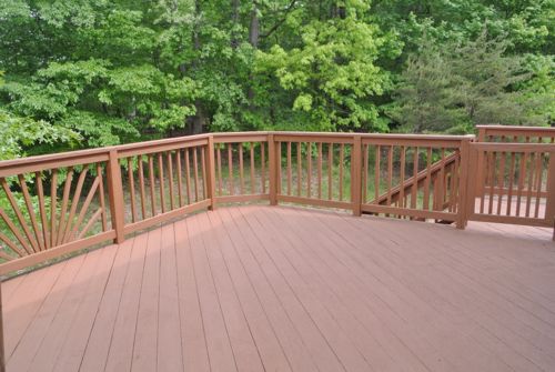
We found that the deck needed a little more than 48 hours to completely dry. It’s only been a few days since the work was completed, but already I’m extremely pleased with results. The deck looks like a hybrid between composite and wood. All the cracks are filled in creating a nice, even surface. Plus, I’m not worried about splinters anymore.
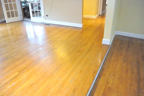
If you read my most recent Pro-Follow, you know that I’m working with a new-to-OPC hardwood flooring contractor named Danny Riter. Danny is the owner of Signature Hardwood Floors Inc., and he and his crew are in the process of refinishing an existing hardwood floor and extending it throughout the kitchen. You can read more about laying the new floor and weaving it in with the old here:
What’s even more exciting than the new floor is seeing Danny and his crew refinish the existing hardwood floor to make it look like new again. Today’s Pro-Follow will focus on how the guys removed the existing finish and sanded the floor. There’s a lot of work that goes into creating that “blank canvas”. Look for a complete Project Guide for refinishing a hardwood floor, including staining and finishing early next week.
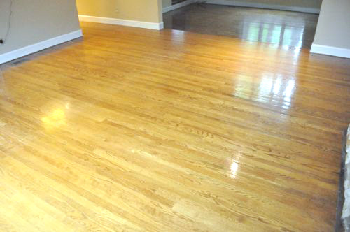
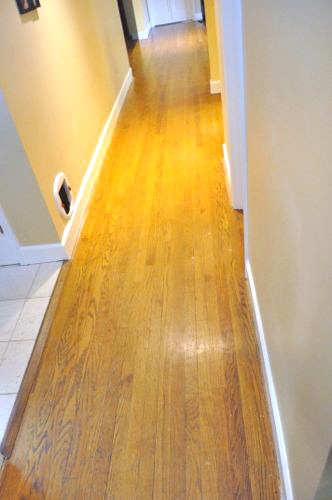
Last time we left off the guys had laid the new hardwood floor in the kitchen, pantry and a short hallway.
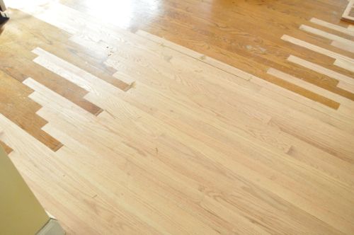
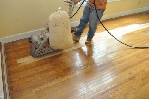
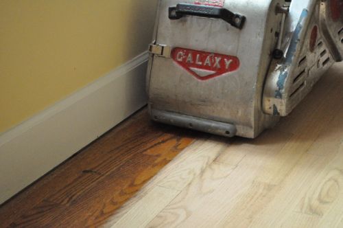
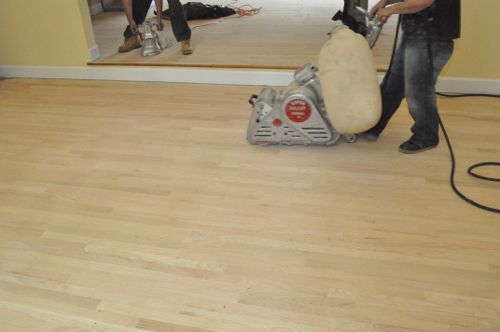
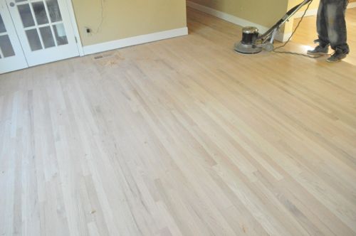
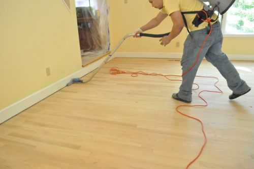
Step 1: Drum Sand Floor
To remove the majority of the existing finish and stain, Danny’s crew used an 8″ drum sander. They started off with a 36 grit sanding belt.
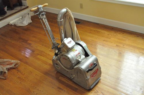
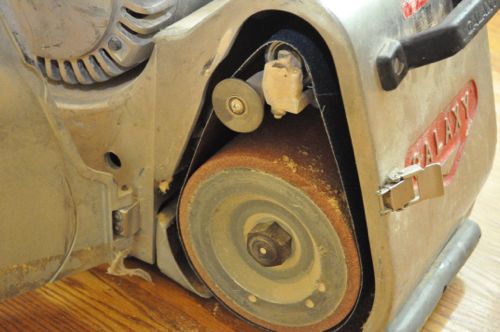
The sander is a pretty simple machine. The handle enable the operator to maneuver the sander, and the lever engages the sanding belt against the floor. The bag can swivel to either side, and it captured a fair amount of dust.
Pro-Tip: Always sand in the direction of the boards.
Pro-Tip: Always put the sander in motion before engaging the belt against the floor to prevent uneven sanding.

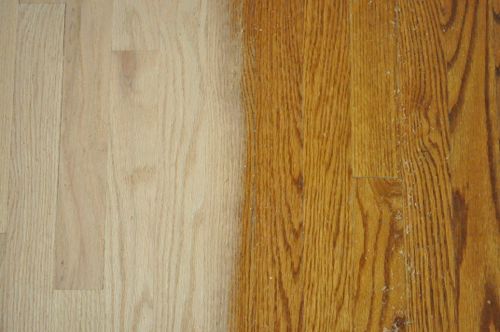
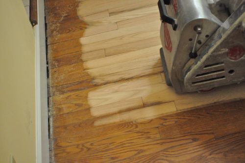
For the most part, two or three overlapping passes was enough to completely remove the old polyurethane and stain. Occasionally the guys found a low spot and had to hit it again. Danny’s crew would sand 3/4 of a room facing one direction, then sand the rest of the room facing the opposite direction.
Pro-Tip: Each sanding belt covered approximately 250 sq ft. before the guys swapped it out.
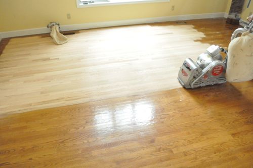
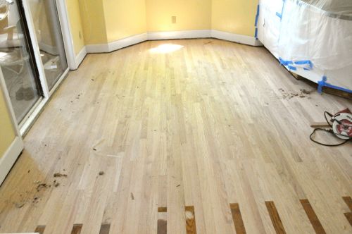
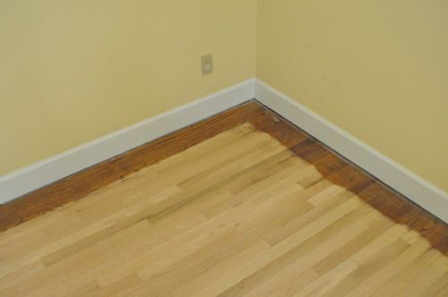
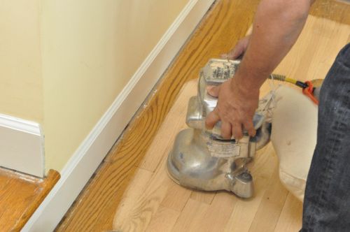
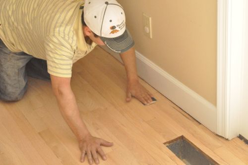
The belt sander can only get so close to walls, corners and other tight spaces. The guys were very careful not to bump the sander and thereby damage the floor. They also avoided going over the floor vent openings with the drum sander.
The result was about a 5″ perimeter around most rooms and the hallway. The drum sander was too large for a few of the closets so the guys couldn’t use it there either.
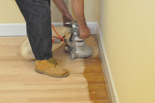
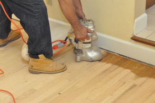
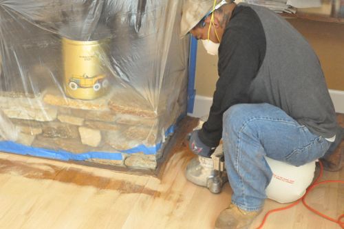
Step 2: Sand with Floor Edger
Next, Danny’s crew used a pair of floor edgers which enabled them to get right up against the walls and into areas with limited space.
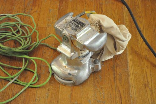
Like with the drum sander, they used 36 grit sanding discs.
Pro-Tip: The guys double-stacked the sanding discs so that when the first one wore out, they could just rip it off and get right back to work.
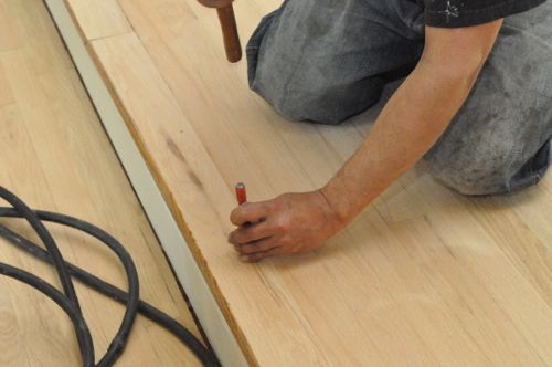
Step 3: Set Nails
Danny’s crew checked the floor for nails and used a nail set to sink them below the surface of the wood.
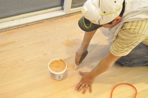
Step 4: Putty holes and Cracks
After sanding, the guys used Woodwise wood filler to fill nail holes and any noticeable cracks.
Step 5: Vacuum and Repeat
While the wood filler dried, the guys gave the floor a quick vacuum.
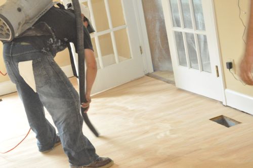
Next, they repeated the process (drum sander and floor edger) with 80 grit sanding belts and discs.
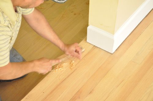
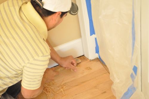
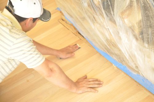
Step 6: Hand Scrape
The floor edgers move in a circular motion, and although it’s difficult to see before staining, they leave swirl marks in the floor. To remove those and get in even tighter into corners, the guys used scrapers to remove a thin layer of wood.
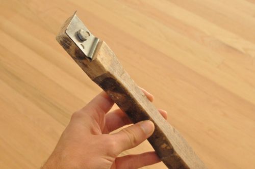
Pro-Tip: Use a file to hone the scraper edge periodically for best results.
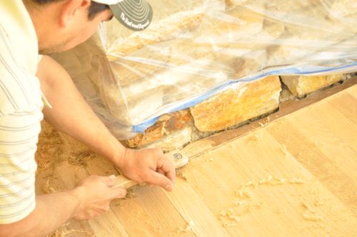
The scrapers were also great on stair-nosing and transition strips.
Step 7: Lightly Sand
After scraping, Danny’s crew did some light sanding with 180 grit sandpaper to ensure a nice, smooth surface.
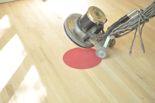
Step 8: Buff Floors
Lastly, the guys broke out a floor buffer and a 120 grit buffer pad. They quickly went over all the floors, getting as close to walls and corners as possible.
Step 9: Vacuum Clean
As you can imagine, all this sanding can create a significant amount of dust. Fortunately, most of their sanders have a vacuum hookup or a dust bag. Even so, the guys carefully vacuumed and dusted all the surfaces (not just the floor) to eliminate as much dust as possible. Otherwise, the dust can settle in stain or poly and flaw the finish.
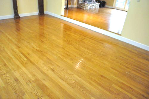
Stick around! The next Pro-Follow will cover how the guys applied stain and finished the wood for a beautiful, long-lasting floor.
I’m excited to kick-off another Pro-Follow and to introduce you to a new pro named Danny Riter. Danny is a hardwood flooring contractor and owner of Signature Hardwood Floors Inc. Danny brings more than 20 years of experience in the industry, and he’s very knowledgable. I hope to bring you more Pro-Follows with Danny in the days to come. For this project, the homeowners have brought Danny in to replace a tile kitchen floor and refinish the existing hardwood floors to match.
If your interested in learning more about installing hardwood flooring, follow that link to see our Project Guide for full details.
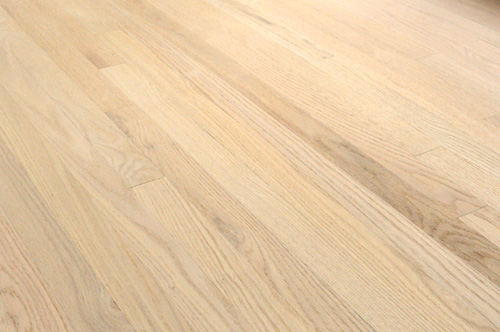
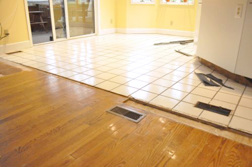
Danny’s crew will be refinishing a sizable area including three rooms, a hallway, laundry room and several closets. The old floor is a 3/4″ x 2-1/4″ oak, and it’s in fairly good shape. The guys will sand the existing floor down and finish everything (old and new) together for one, consistent look.
If you look closely, you’ll notice the shoe molding has already been removed in these pictures.
Danny’s crew is taking up the kitchen tile and the two layers of plywood underlayment before laying the new boards, and I’m excited to see how they blend the old and new floors.
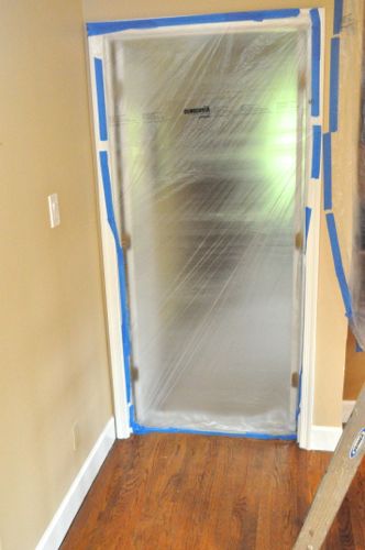
Step 1: Setup Plastic Barriers
Refinishing floors can create a significant amount of dust so before any work began, Danny’s crew covered just about everything in plastic.
Pro-Tip: Change your furnace filter after refinishing your floors.
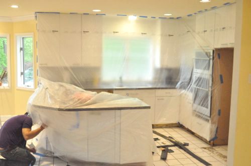
These guys were thorough, covering doors, light fixtures, shelves, cabinets, the fireplace, and more.
Step 2: Demo
After the plastic was setup, the guys got started on removing the old tile floor.
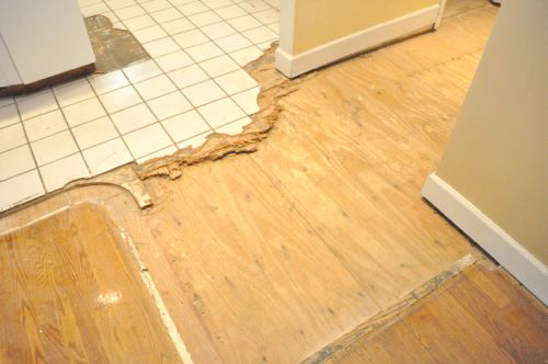
When possible, they removed large sheets with the tile still fixed in place.
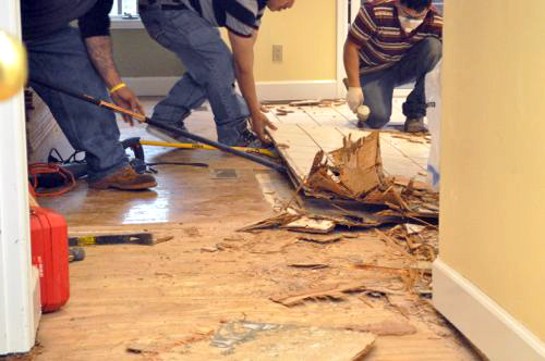
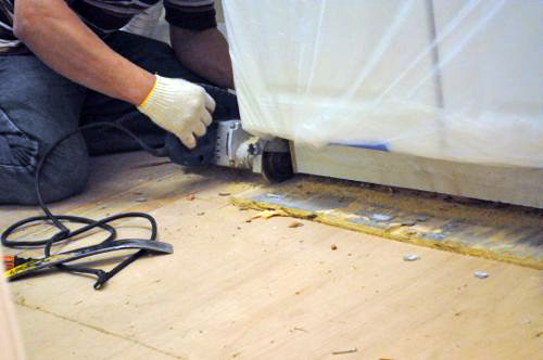
Some of the plywood extended underneath the cabinets. Rather than pull up the cabinets, Danny’s crew used a handy flush-cutting circular saw to cut through the plywood.
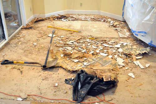
It was slow going but eventually the tile floor was completely removed. As the guys cleaned away debris, they were careful to remove or pound in any protruding nails.
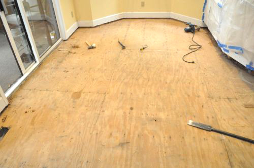
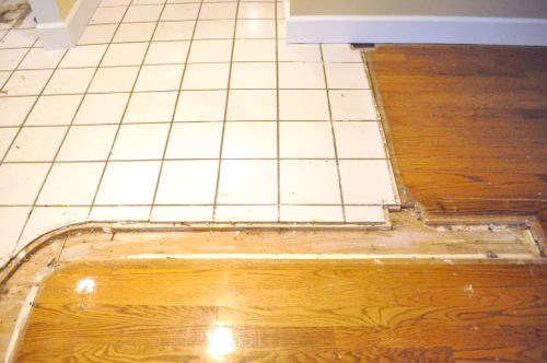
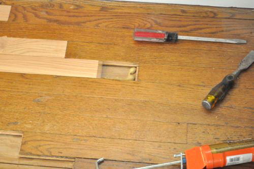
Step 3: Remove Some Floorboards
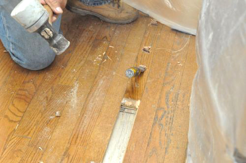
To seamlessly transition between the old floor and the new floor, the guys need to remove specific floorboards to be able to thread in new ones. Otherwise, the guys would have to incorporate an ugly transition strip.
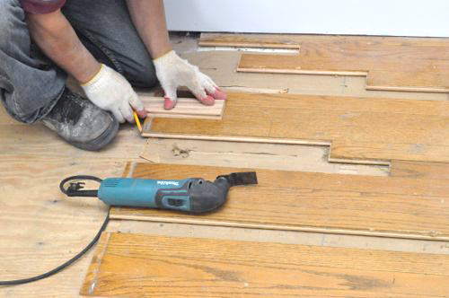
There’s a couple of different ways to remove a single floorboard. For instance, you can set a circular saw to the appropriate depth and make a series of cuts until there’s enough room to pull the board free. In the picture below, one of Danny’s crew is using a hammer and chisel to slide a board out, and as you can imagine it takes a lot of pounding.
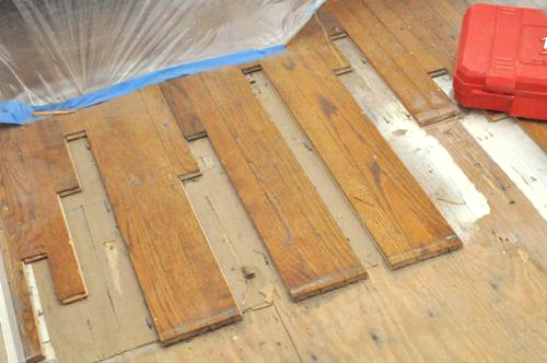
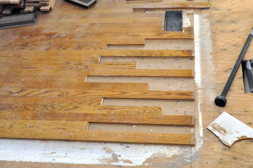
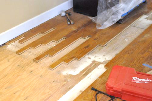
You can see how Danny’s crew is removing floorboards enough to stagger the joints.
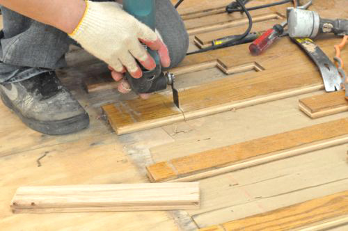
In a few instances, the guys used an oscillating multitool (OMT) to carefully cut a board and create a new joint.
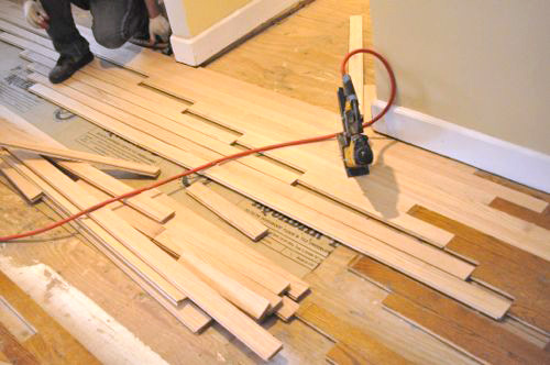
Step 4: Begin Laying New Boards
Next, Danny’s crew measured and snapped a chalk-line to provide a reference point. The guys setup the first new board and measured the distance to the chalk line to ensure it was straight.
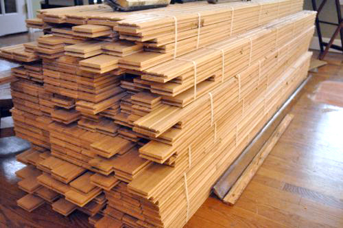
Pro-Tip: Be sure to let the new board fully acclimate before installing.
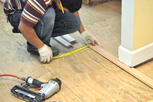
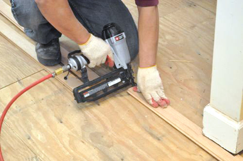
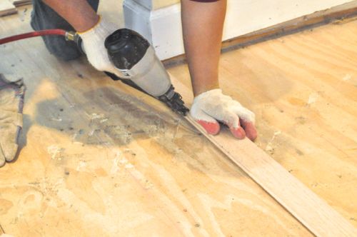
After they lined everything up, the guys toe-nailed the first board with a finish nail gun and 16ga, 2″ nails.
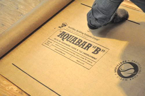
Step 5: Unroll Underlayment
Underlayment reduces squeaks and creates a vapor and moisture retarder. The guys used Aquabar type B underlayment.
Step 6: Continue Laying Boards
Danny’s crew continued laying boards in the field, threading them between the existing floor boards. After three rows, the guys were able to break out a Bostitch flooring stapler to anchor the boards.
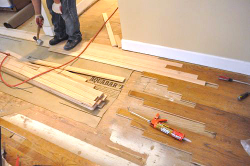
Where a new board was directly against an old floorboard (and therefore only able to place a few staples on the open end), the guy used a dab of construction adhesive to help lock it in place.
In this way, the guys began laying new floor boards and “weaving” them in with the old flooring.
On the next Pro-Follow I’ll be covering how Danny’s crew sanded the existing floor to make it look like new so stick around!