
Welcome back to our Basement Remodel Pro-Follow. I’ve been shadowing expert general contractor Joe Bianco and his crew as they finish an unfinished basement. This is the third installment in our series.
- Day 1 covered framing out the basement into four distinct rooms.
- Day 2 covered the plumbing rough-in, which included re-positioning an underground drain for the bathroom shower.
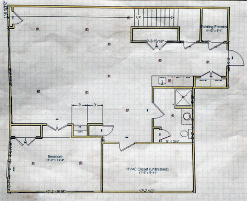
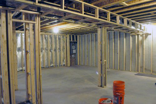
Today I’m covering the electric rough-in, following a subcontracted master electrician through a two-day process. We’ll be reviewing installation of a new sub-panel, recessed lights, receptacles, and more. Here’s a diagram of the plan for this space and a picture post-framing to refresh your memory on our progress to date.
Step 3: Plan the Electrical Rough-In & Obtain Permits
The day before the electrician began work, he came out and walked the floor with Joe and the homeowner. Together, they discussed the vision for the basement. As the homeowner and Joe described the basement’s individual functional areas, the electrician translated their discussion into electrical markings throughout the space, making recommendations to keep the basement in line with local codes. In this way, the homeowner and the contractor team came to a solid understanding of where all receptacles, recessed lights, cable connections, smoke detectors, and light switches would be placed, and where the sub-panel that would power the basement would be located.
In finished areas, code requires that outlets be spaced such that an outlet is reachable within 6′ horizontally of any place on an unbroken wall. This means that the maximum spacing for receptacles is every 12 feet; however, in practice, electrical outlets are often placed closer together for convenience. The code also specifies that Ground Fault Interrupters (GFI)-protected outlets must be used in all unfinished spaces, as well as in wet locations, such as the bathroom and wet bar.

Pro-Tip: Although not required by code, receptacles, switches and cable connections are typically placed 15″, 48″ and 62″, respectively off the ground.

SD indicates a smoke detector and R indicates recessed lights.


This electrical plan not only ensures the right expectations for the homeowner, it also allows the master electrician to obtain a permit for the job.
Step 4: Install the Electrical Components, Per the Rough-In Plan
Note that throughout the following steps, the electricians are fully cognizant of the plan for the space. Included in that plan is the installation of a sub-panel that will power the basement. Accordingly, as the crew runs cable to connect receptacles and cans, the source of any given circuit in this basement is the sub-panel, which itself will be tied into the main breaker panel in Step 4f.
Step 4a: Install boxes for Outlets, Switches, and Smoke Detectors
The next day, two electricians arrived and began by mounting boxes for outlets, switches and smoke detectors. Installing boxes first gives the electricians a solid understanding of which studs will need to be drilled to run Romex for the circuit.

As they worked, the team considered challenges with individual placements. For example, they added an extra 2×4 to move this box out from the corner, making it easier to hang drywall.
![]()
Pro-Tip: New code requires a neutral wire be located at every switch, because neutral is required for some newer dimmer switches to function. In the past, an electrician could run a 2-wire “switch cable” from an overhead lamp down to the switch. This cable would bring power down to the switch on the white wire, and take “switched power” back to the lamp on the black wire. (This could be remembered with the saying “white going down, black coming back.”). This switching strategy does not bring a neutral wire to the box. When the crew runs Romex for lights in this basement, the circuit will originate at the sub-panel and travel to the switch boxes first, before heading on to the lights, resulting in a neutral wire at both the switch and the lights.

Step 4b: Install Overhead Recessed Cans
The crew installed “new work”, IC (insulation contact) recessed cans, spacing them out evenly by measuring the area into thirds. For instance, in a 12 x 12′ space, four recessed lights are positioned in a square at 4′ intervals.
Pro-Talk: Recessed cans are rated IC (insulation contact) or Non-IC (no insulation contact) depending on whether the fixture can come in direct contact with insulation. Most Non-IC cans require a 6″ air gap between the can and the nearest insulation; whereas IC cans can have insulation packed tightly against them. IC cans are required in top-floor installations, but may be used in any installation.

Part of the electrical planning process focused on positioning switches along expected walkways. That means that as the homeowner enters a room, the switch is right where they’d expect it to be, and as they leave the room, they’ll never have to backtrack to turn off any lights. For instance, as they enter the basement, light switches are there to illuminate the large, entertaining area. These same lights can be turned off by another switch by the bedroom door. The electricians achieved this by running 3-wire between the two switches.
There are many articles already written that describe how to wire a three-way switch to accomplish this. Here’s a great one at The Home Improvement Web.
Pro-Talk: The term “2-wire” refers to a cable with a hot, neutral and ground wire within the wire sheathing. “3-wire” includes these wires an additional red wire called a traveler or signal wire, required in three-way switch configurations (where two switches control the same light), as well as in linked smoke detectors.
In this diagram of the entertainment area, the blue circles represent recessed lights, the green boxes indicate switches and the numbers denote the type of wire (2-wire or 3-wire) between them.

Step 4c: Drill Studs and Joists for Wiring
The crew used a 3/4″ auger bit to drill holes through the studs. While not required by code, most electricians will place these about waist height to avoid drywall screws.
Pro-Tip: Romex must be kept at least 1.25″ away from the nailing face. If wire is closer than 1.25″ to the nailing face, protective metal plates must be installed to ensure nails and screws will not penetrate the wire.

TJI joists are convenient for electricians because they feature knock-outs for running utilities, eliminating the need for drilling.

Step 4d: Run Romex Throughout the Basement
The electricians ran 14/2 (14 gauge, 2-wire) wire for most of the basement, securing the wires with insulated staples at 4′ intervals. Typically the crew put 8 to 10 receptacles on a circuit. The bathroom, wet-bar, refrigerator and microwave all receive dedicated circuits and are wired with 12/2 wire.
Additional Information: Below are the National Electric Code’s rules for wire gauges and over-current protection requirements. Note that I’ve simplified this explanation to keep it brief. There are actually more complex restrictions based on the distance the wire is being run and the type of wire being used. However, for most residential installations, the following applies.
- 14 gauge wire – 15 amps maximum – standard lighting and receptacle circuits
- 12 gauge wire – 20 amps maximum – appliance circuits
- 10 gauge wire – 30 amps maximum – water heaters, some HVAC equipment
The code generally allows for circuits to be loaded at 80%, meaning a standard 15-amp circuit can be loaded with 13 amps worth of fixtures and receptacles. The number of receptacles allowed on a circuit varies by district. Rather than specifying a limit for the number of receptacles on a circuit, the NEC uses a square-footage rating to determine the number of circuits required for a space. Generally, a safe assumption is that each receptacle will use 1.5 amps, which equates to eight receptacles per circuit for a standard 15 amp circuit. You should consult the NEC and your local code to determine the requirements for loading in your area.

Pro-Tip: Currently, the color of the sheathing indicates the wire gauge. White wire is 14 gauge, yellow wire is 12 gauge and orange wire is 10 gauge.

Smoke detectors must be wired with 3-wire so that if one alarm goes off, the others will too. The third wire serves as a signal wire between the individual detectors to synchronize their alarms.

It’s good practice to label wires to avoid confusion over which is which.


Step 4e: Tie in the Outlets, Cans, and Switches
After all the wires were in place and secured with staples, the electricians began to tie-in the boxes.

Pro-Tip: Several electricians I’ve spoken with all agree, the most common DIYer mistake is failing to properly twist wires before adding the wire-nut.
Pro-Talk: The term “tied-in” means ready for a receptacle or switch to be installed.
Notice how the white sheathing stops just after the wires enter the box. For spliced wires, the wires are stripped back evenly, twisted together, cut at 1/2″ length and then wire-nutted together.


Step 4f: Install the Sub-Panel
All of the new lights, receptacles and fixtures will be powered off a new sub-panel because the old panel didn’t have enough room.
To connect the two panels, the electricians ran #4 SER aluminum wire, which is capable of providing 60 amps of current. You may not be able to see them, but there are four wires within the gray sheathing: 2 hot, 1 neutral and 1 ground.


The new sub-panel is sized to fit between 16″ oc studs and held in place with screws.

All wires entering the sub-panel are secured with wire connectors.

The electricians use NOALOX, an anti-oxidant joint compound, for all the #4 SER terminations.
Pro-Tip: NOALOX is an oxidation inhibitor. When aluminum oxidizes, it becomes more electrically resistant. As this occurs, current flowing through the wires generates heat. Over time, oxidation can lead to a fire risk. Properly applying Noalox or another oxidation inhibitor to aluminum connections mitigates the risk of fire, and is required by code in most aluminum wiring applications.

Here’s what the panel looks like after some of the wiring has been partially completed. You can see the large, white-striped wire connecting to the neutral bar (left), the two red-striped wires providing power (center), and the ground wire is obscured behind other ground wires (right). This panel uses square-D breakers and provides 20 spaces.
Note that in sub-panels, the ground bus and neutral bus are separate. In the main panel for a house, ground and neutral are tied together on the same bus.

At the other end, the #4 SER connects to the existing panel with a double-breaker.


Pro-Tip: Avert your eyes when you flip the breaker to power the sub-panel for the first time. If there was an error, a bright flash may occur, temporarily blinding you.
Step 5: Electrical Rough In Inspection
The crew double-checked their work, tested a few connections, and will wait for the inspector to give the sign-off before making final connections at the main breaker panel.
Pro-Tip: In virtually every jurisdiction, permits and an electrical rough-in inspection are required prior to installing drywall. Failure to get a proper inspection may lead to the inspector later requiring that all drywall be removed. This can be extremely costly, so this step should never be skipped.
I hope you’ve enjoyed this most recent Pro-Follow update. Subscribe to our email or RSS feed to stay current on this and future projects.

I just went through adding a 40 amp sub panel to my garage. It was like dejavu reading this thing. Great pro tips sprinkled in.
Do you know why they picked alum over similarly rated copper for the feeder?
I would guess the aluminum is significantly cheaper. It seems to be pretty standard, any sub panels I have seen installed (given my very limited experience) have always been supplied with aluminum wire.
I’m sure it was cost. Aluminum is significantly cheaper than copper right now, but is not to code for most applications. It is only acceptable in low-gauge cables. David has a good comment below on Noalox which I’m going to respond to as well.
Great information. I love the mention of all the code requirements. Most DIYers completely ignore codes (and permits for that matter). Electricity is the one thing to to NEVER cut corners on. It could mean someone gets seriously hurt…or worse….
I agree with the code for the most part… but some things really bother me (like the newer requirement to have a GFCI protected outlet on the ceiling of the garage…)
I don’t really want to turn this into a permit discussion but I think cities/counties need to make getting permits easier and cheaper for homeowners. You’re right Jake, most ignore codes and permits. A lot of people only get permits for things that are visible from the street (and can easily be busted on). I wish there was a way to make people want to pull permits and do things the right way.
I agree, and I will admit that I havent pulled permits for some stuff on my house when I should have… but then again, I was FIXING someone else’s busted work, which included leaving a live wire hanging out in the garage, and not a single three way switch working.
I also try to make sure that all of my work is code compliant, so if I did pull a permit, it would pass. I will make sure to pull the permit when I re-finish my basement, as that’s a bit more major than a few lights and outlets.
The irony is that historically contractors lobbied the government to regulate the construction industry to make it more difficult for homeowners to do projects themselves. It was a job security move for the professionals. That’s not to say that safety regulations don’t have their place in the industry, but I agree that as a homeowner it’s often more hassle and money than it’s worth to get proper permitting.
In my area, part of the problem with getting people to properly permit are the alternatives. Our code enforcement officer is very hands-off and only enforces the code when a specific complaint is made – they don’t actively seek out violators. When we put our deck on we did the right thing and paid for our permits and got our work inspected. Once we were all done our house was reassessed and now we are paying taxes on the deck as well. Numerous others in the community have installed decks (and large sheds and who knows what else) without permits, but haven’t had the reassessment and increase in taxes, let alone the permit fees. I’m a believer in doing the right thing and karma, so I suck it up when necessary, but people definitely aren’t motivated to pull permits around me because there is no detriment at this point (we’ll see what happens when we get a new code enforcement officer).
In our county, homeowners are not allowed to pull electrical permits for their own work. This was specifically lobbied for by the electrical trade association here. Just one county west, homeowners can take a standard test and obtain permits for almost all work within their own home (certain jobs, like adding new service, I believe are still off-limits for the DIYer). This inability for homeowners to get even basic permits promotes non-compliance far more than if the county simply would let homeowners do some of the most basic work themselves. Most electricians in our area know that at least some work happens off-the-books. The process that ostensibly makes us “safer” is actually turning out to have the opposite effect.
Another big error I have seen is that when the wire is stripped for the connection the stripper leaves a nick in the copper, sometimes very deep (deep enough to allow the wire to snap with minor handling). I just had to re-make every outlet in someone’s basement because of this… it wasn’t fun, and some of the outlets DID have broken wires on them (and that was all done recently).
When stripping, USE A HIGH QUALITY STRIPPER, if you nick the wire in any way (this includes losing a few strands of stranded wire) then it could become a starting point for a failure, and you should probably try again.
Also, use the screw terminals, they’re reversible without damaging the wire, and more reliable. But don’t just stick the wire in there wrap it around the screw, if you have more than one wire to hook up to a terminal, you need a wire nut and a pigtail.
cool post. One of the breakers is labeled “elevator”. This must be one heck of a house…
Great catch. The elevator is a closet elevator, which is definitely becoming more popular around here. This is actually a townhome, and while I don’t know the homeowners, I wouldn’t be surprised if it were in a retirement community. One of the more popular things around here (because land has become so expensive) is to put small elevators in town homes to make them more suitable for folks with mobility challenges. The nice side-effect of this is that as it becomes more standard, there’s less cost. At some point we’ll have to do a post on the residential elevators. They do require inspection and maintenance at least once per year. In retirement communities around here, sometimes that cost is covered by a condo association, since all the homes have elevators and they can negotiate a better fee with the maintenance company.
Whoa this house has an Elevator? Must be huge
This is a relatively big house, but not huge. Take a look at my note above. One thing that is becoming popular are elevators to keep homes accessible for the elderly and mobility impaired. We’re big fans of this move, even in smaller homes.
Also how come all the writing on the panels labeling the switches always looks like a 10 year old wrote it. Ours has the same writing style on it. Exactly the same! Do all electricians have the same writing style.
Kim wrote a post some time back on making a printed label for your breaker box. It’s a fun activity when you’ve got some spare hours. Figure out the breakers for everything in the house and make a nice looking, thoroughly documented label.
I think the new code requiring neutral wires everywhere is a good idea. I know I’ve added a lot of dimmer switches around our home and we use them a lot.
I am a fan of this too. Besides what the post mentions, there is also the option to run 3-wire down from the lamp (hot and neutral going down, switched hot coming back). This can be a good configuration if for some reason you’re adding a switch to an overhead lamp that didn’t already have a switch (e.g., converting a pull chain lamp to a wall-switched lamp).
You glossed over what I would consider the important point about using Noalox (or any electrical rated aluminum anti-oxidation compound). The reason you HAVE to use this is due to aluminum oxide being very resistive. Which means that if you do not prevent oxidation then your contact point will get more and more resistive. As you increase the current through a resistive load it heats up and can cause a fire (just like an electric heater).
The important information is that back when most of the house wiring use to be aluminum this was a common problem when someone would change a receptacle. They would skip this part (saving money or just ignorant of the process) and eventually the house would go up in flames.
David, you are absolutely right. It’s worth mentioning that Noalox brand is short for “No Aluminum Oxidation” as far as we know. I will update the post to add in this as a “Pro-Tip”
I know you don’t want this to be a discussion on permits but several comments hit the nail on the head. As long as the incentives for not getting a permit outweigh the incentives for getting one, there are going to be people who won’t comply.
All this permit mess. I’m just going to rewire my garage all kinds of crazy and then drywall over it just to confuse future occupants of my home. Seems to be the approach that the builder took when it was first built anyways.
This literally got me to laugh out loud. It seems like there’s always at least one switch somewhere that “goes to nothing” in whatever house we’ve owned.
That’s hilarious b/c I feel the exact same way. They leave you scratching your head wondering why (almost) the entire kitchen runs back through the light fixture.
We’ve lived in our house for about 4 years. I use the hall bathroom the most, and every time I walk in and try to flip the light on, I’m reminded of how lazy the electrician was. If you’ve never thought about it, light switches are always on the opposite side of the door from the hinges. Not this powder room. It’s an outward swinging door with the switches on the hinge side, because all the other electrical work is on that side of the bathroom. When you walk in, you instinctively reach for the lights, and remember that your house was built by an idiot or a sadist.
I don’t know what code requires that my garage outlets be 4 feet off the ground, but it’s really annoying. It’s not like there’s a chance that four feet of water will flood my garage and not cause any problems with the outlets at standard height inside the rest of the house.
I put all of my garage outlets at that height. It is perfect for over bench tops and for a lot of my large tools. They are easy to see in a garage that has a lot of things built onto the walls. The only low outlet I want is one in the middle of the floor for the table saw but that’s hard to do without trenching out the floor.
Hi. I was looking at the Joe Blanco Basement Remodel Pro-Follow. Loved Day 1 and Day 3 the information they provided is awesome. I’m looking to find Day 2 Plumbing Rough-In which included re-positioning an underground drain for the bathroom shower. When I click on the Day 2 link it takes me to:How to Remodel a Bathroom from the Ground Up by general contractor Steve Wartman. Anyway to see the Day 2 follow with Joe Blanco?