This is a great tutorial that I put together in March of 2012 on How to Repair a Medium-Size Hole in Drywall, and you can find this along with other top-notch articles in the Best of OPC section found in the right sidebar. If you read through the comments, you’ll find some alternative drywall repair suggestions, and some of them are valid options. However, the method I describe here is tried-and-true, and it results in a flawless, durable patch every time. Furthermore, a number of drywall contractors confirm that this is how they tackle a medium sized repair.
Repairing drywall is a great do-it-yourselfer task because tools and materials are cheap, and there’s very little risk (to you or the house). Plus, if you can master the repair, it’s a skill that will serve you well no matter if you own or rent. So before you call the local handyman next time, give yourself a chance to tackle this basic, home improvement project.

Materials List
- Drywall (see below)
- Mesh tape (see below)
- Setting compound (see below)
- Backer boards (see below)
- 1-1/4″ Drywall screws
Drywall: Also called sheet rock or gypsum board, drywall is available in several sizes and thicknesses. Purchase a piece bigger than the hole because you’ll be squaring it out (and making it slightly larger). Home improvement centers often sell 2 x 2′ sections which are great for making repairs. Drywall is commonly available in 1/4″, 1/2″, 3/8″, 5/8″ and 3/4″. Most interior walls have 1/2″ drywall, and ceilings are typically 1/2″ or 5/8.” The thickness of the new piece should match the existing drywall.
Mesh tape: I used a fiberglass mesh tape for this repair. Paper tape is another alternative, and it results in a stronger joint. If you expect any sort of movement or stress on the joint, paper tape will better resist cracks. If you use mesh tape, I recommend avoiding the pre-mixed joint compound (more on that next).
Setting Compound: Setting compound (or hot mud) is a powder that comes in a bag and needs to be mixed with water. Unlike joint compound which dries through evaporation, setting compound dries through a chemical reaction, shrinks very little and dries very hard. Setting compound is differentiated by drying time (in minutes), and you’ll find 5, 20, 45, 90, etc. Setting compound is nice because you’re able to apply a second coat without waiting too long. I purchased an easy-sand, 5 minute compound. If you’re a novice to patching drywall, go with a longer drying time.

Backer Boards: Repairing a medium-sized hole in drywall calls for adding a new piece of drywall. To secure this new piece, you’ll need some sort of backer boards, and I used small pieces of 1/4″ plywood.
Tools
- Utility knife
- Drywall saw
- 6″ Drywall knife (pictured)
- Drill / driver
- 100 grit Sandpaper

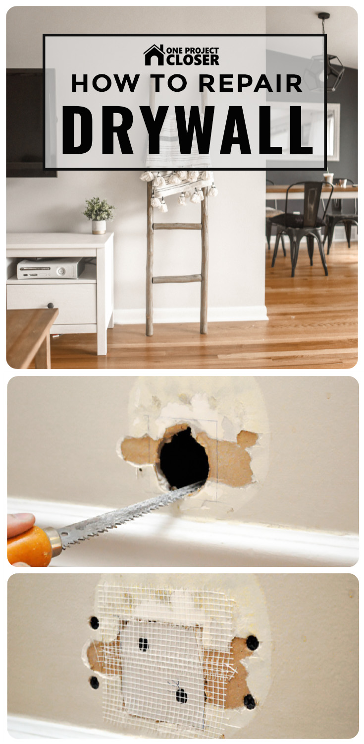
Step 1: Square the Hole
This is the hole right by my front door. I’d guess the previous owner opened to door too hard, and instead of repairing the damage, covered it with a plastic wall bumper. Cutting a circular (or other oddly shaped) piece of drywall is tedious. Instead, I like to widen the hole into a square or rectangle.

I recommend scoring the edges with a utility knife before you start sawing.


Step 2: Secure the Backer Board
This is a medium-sized hole, and it’s impossible to simply fill the void with compound. I need to add a new piece of drywall, and to fasten the drywall, I need some sort of backing or furring strip. To accomplish this, I slide a piece of 1/4″ plywood into the hole.

Carefully, I start a drywall screw that allows me to easily hold the plywood across the opening.

Next, I put in four drywall screws to hold my backer in place.

Screws should be countersunk just below the surface of the drywall.


Alternate Method
It just so happens that I have a second hole in my basement. For this hole, there is a stud nearby so I cut the drywall to expose half the stud. This gives me a nice nailing surface of the left side. Now I just secure my backer board to the right side.


Step 3: Cut a New Piece of Drywall
Use your utility knife and/or drywall saw to cut a new piece of drywall that fits into the hole.

Step 4: Cover the Joints with Tape
I covered the entire new piece of drywall and all the edges with mesh tape. Often you’ll see people cover the screw heads too (which is fine but I didn’t).
Step 5: Mix Compound and Apply First Coat
It doesn’t take much compound to cover a hole like this. I mixed a little powder and water until the compound had a thick, “mashed-potato” consistency. This is important because if the compound is too wet, it’ll result in a poor bond. Sloppy mud is also a pain to work. Keep adding powder (or water) as necessary until your satisfied.
Using the 6″ drywall knife, I applied the first coat. Make sure you embed all the mesh tape, and try to eliminate any air pockets.


Step 6: Second Coat
While the first coat dried, I mixed up another small batch of compound. I didn’t bother to sand in between the first and second coat, using my knife to check for any high points. If you’re really good at patching, you can finish everything off in two coats. I fully expected to need a third coat. After the second coat dried, I used 100 grit sandpaper to feather the edges. The goal is to create a seamless transition so you’ll never know the wall was damaged.

Step 7: Final Coat
When you apply the final coat, try to make it as smooth as possible. It’ll save you from having do a lot of sanding.

Step 8: Sand Smooth
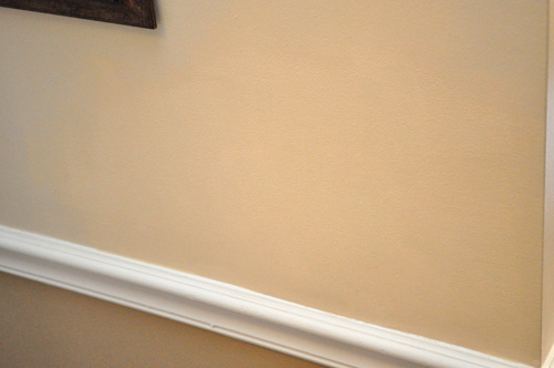
Feather all the edges by sanding them smooth, and give the rest of the patch a once-over to eliminate any dimples or ridges. Feel everything with your hand to make sure it’s all even.

Step 9: Prime
It’s really important to prime your drywall repair because compound will absorb paint differently, and even if you did a good patch job, without primer it’ll be obvious.

Step 10: Paint
We keep a little leftover paint for each room for just this purpose. I like to roll the paint because I can notice brush strokes, and again that’s a giveaway that you patched the drywall. Rolling the paint gives it the same texture as the rest of the wall.
If you enjoyed this project, why don’t you check out the other home improvement how-tos available in the Project Guides section.
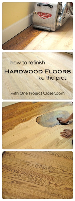
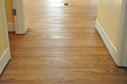
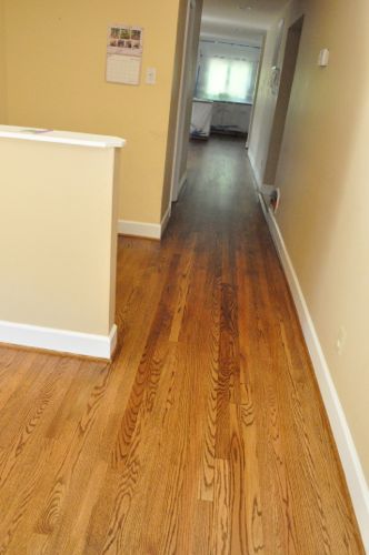
Welcome back to our latest Pro-Follow series focused on how to refinish hardwood floors. Refinishing a hardwood floor is a great way to bring new life to a floor that is showing too much wear and tear or if the finish is no longer protecting the floor. It’s also a necessary part of extending an existing hardwood floor like we showcase here.
All of our Pro-Follow articles are the result of shadowing expert, professional contractors on actual job sites. There’s no better way to learn about home improvement than straight from the guys working in the field with decades of experience under their tool belt. For this Pro-Follow, I’ve partnered with Danny Riter, owner of Signature Hardwood Floors, Inc. In this article Danny shares the tips and tricks to successfully refinish a hardwood floor. The process includes removing the old stain and finish, proper sanding progression, sanding edges and corners, applying stain, and sealing the floor to protect its beauty for years to come.
If you’re considering new hardwood floors or refinishing an existing floor and you live in the greater Baltimore area, give Danny a call. He and his crew will work with you to provide a beautiful, long-lasting flooring solution. This article is a great example of the knowledge and attention to detail Danny brings to every job. Check out his website for more details.

Tools & Materials
These are the tools and materials that Danny and his crew used for this project. If you’re taking this project on yourself, you can rent the bigger tools at your local DIY center. Links to the manufacturer product pages can be found at the end of this article in the Related Content section.
- Drum Sander
- Floor Edger
- Buffer
- Hand Scraper
- Nail Set
- Vacuum
- Floor Coater and Trim Pads
- Terry Cloth Towels
- Wood Filler
- Stain
- Shellac
- Polyurethane
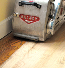
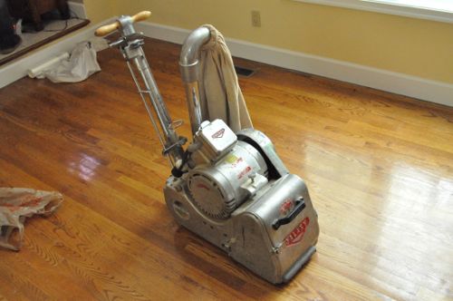
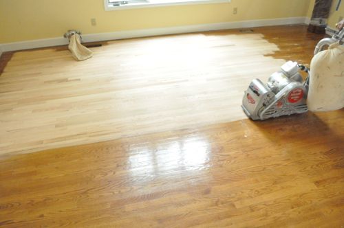
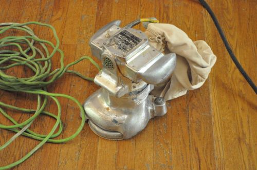
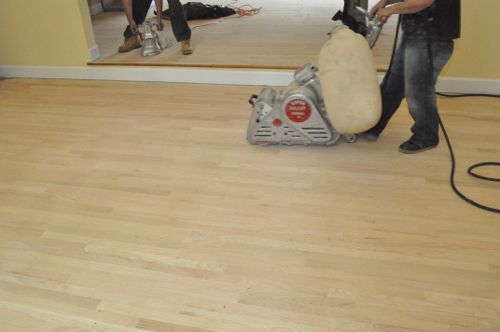
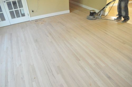
Step 1: Drum Sand Floor
To remove the majority of the existing finish and stain, Danny’s crew used an 8″ drum sander. They started off with a 36 grit sanding belt.
Pro-Tip: Some floors may only have a thin layer of hardwood material, and these floors cannot be refinished.
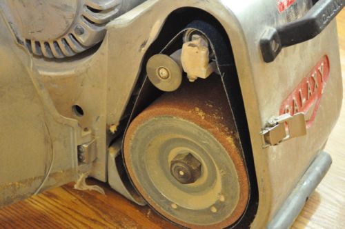
The sander is a pretty simple machine. The handle enable the operator to maneuver the sander, and the lever engages the sanding belt against the floor. The bag can swivel to either side, and it captured a fair amount of dust.
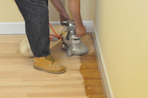
Pro-Tip: Always sand in the direction of the boards.
Pro-Tip: Always put the sander in motion before engaging the belt against the floor to prevent uneven sanding.

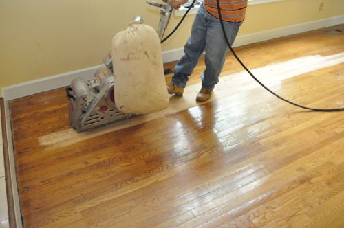
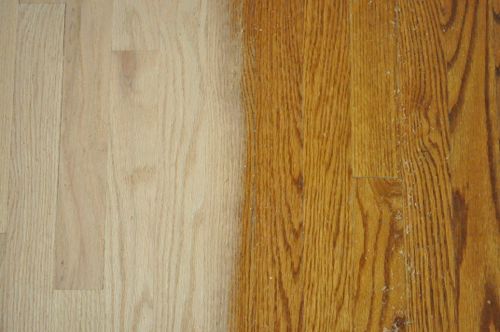
For the most part, two or three overlapping passes was enough to completely remove the old polyurethane and stain. Occasionally the guys found a low spot and had to hit it again. Danny’s crew would sand 3/4 of a room facing one direction, then sand the rest of the room facing the opposite direction.
Pro-Tip: Each sanding belt covered approximately 250 sq ft. before the guys swapped it out.
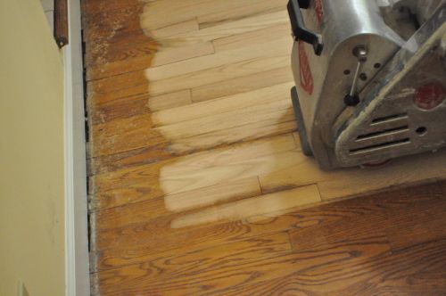
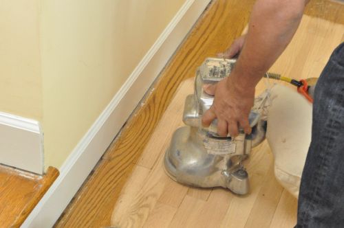
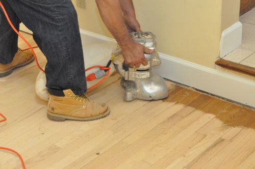
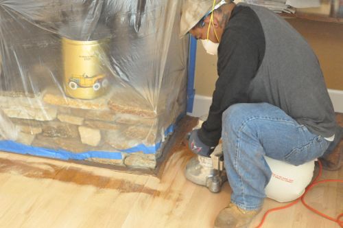
The belt sander can only get so close to walls, corners and other tight spaces. The guys were very careful not to bump the sander and thereby damage the floor. They also avoided going over the floor vent openings with the drum sander.
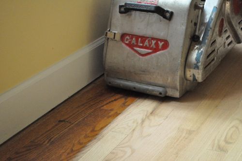
The result was about a 5″ perimeter around most rooms and the hallway. The drum sander was too large for a few of the closets so the guys couldn’t use it there either.
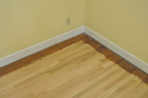
Step 2: Sand with Floor Edger
Next, Danny’s crew used a pair of floor edgers which enabled them to get right up against the walls and into areas with limited space.
Like with the drum sander, they used 36 grit sanding discs.
Pro-Tip: The guys double-stacked the sanding discs so that when the first one wore out, they could just rip it off and get right back to work.
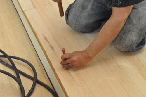
Step 3: Set Nails
Danny’s crew checked the floor for nails and used a nail set to sink them below the surface of the wood.
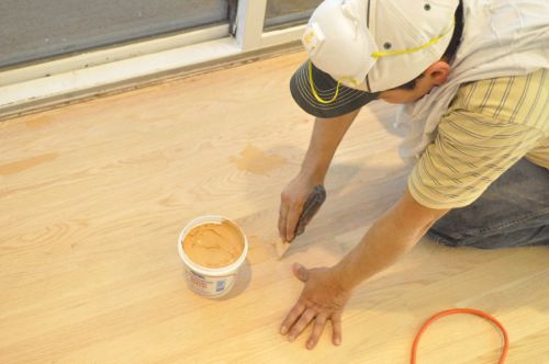
Step 4: Putty holes and Cracks
After sanding, the guys used Woodwise wood filler to fill nail holes and any noticeable cracks.
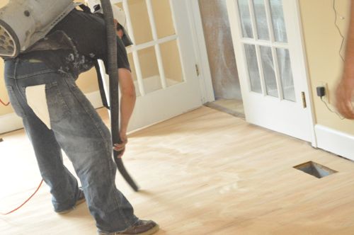
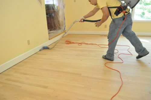
Step 5: Vacuum and Repeat
While the wood filler dried, the guys gave the floor a quick vacuum.
Next, they repeated the process (drum sander and floor edger) with 80 grit sanding belts and discs.
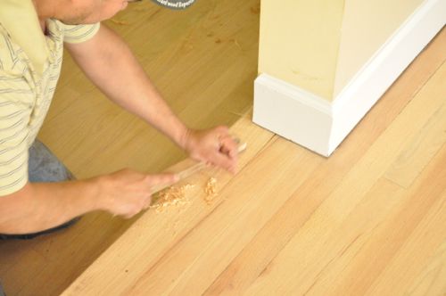
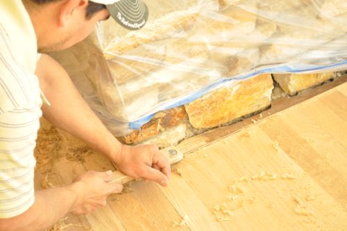
Step 6: Hand Scrape
The floor edgers move in a circular motion, and although it’s difficult to see before staining, they leave swirl marks in the floor. To remove those and get in even tighter into corners, the guys used scrapers to remove a thin layer of wood.
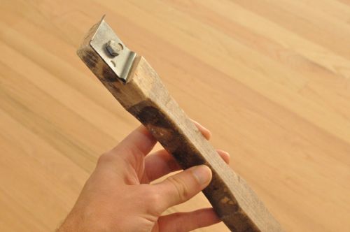
Pro-Tip: Use a file to hone the scraper edge periodically for best results.
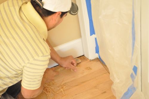
The scrapers were also great on stair-nosing and transition strips.
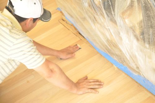
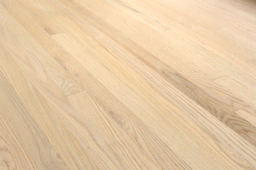
Step 7: Lightly Sand
After scraping, Danny’s crew did some light sanding with 180 grit sandpaper to ensure a nice, smooth surface. They followed this up with more vacuuming.
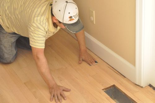
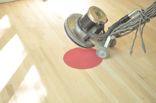
Step 8: Buff Floors
Next, the guys broke out a floor buffer and a 120 grit buffer pad. They quickly went over all the floors, getting as close to walls and corners as possible.
Step 9: Vacuum Clean
As you can imagine, all this sanding can create a significant amount of dust. Fortunately, most of their sanders have a vacuum hookup or a dust bag. Even so, the guys carefully vacuumed and dusted all the surfaces (not just the floor) to eliminate as much dust as possible. Otherwise, the dust can settle in the stain or poly and flaw the finish.
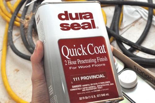
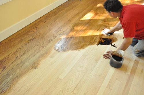
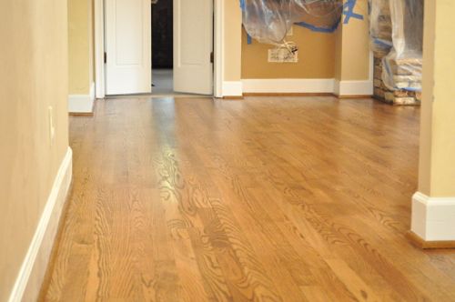
Step 10: Apply Stain
The guys applied DuraSeal Quick Coat, and the stain is called Provincial. It’s a medium brown. Some of the pictures make it look a little yellow, but that’s not the case.
Pro-Tip: Thoroughly shake the container to mix up the stain.
Danny’s crew used Terry cloth towels to apply the stain.
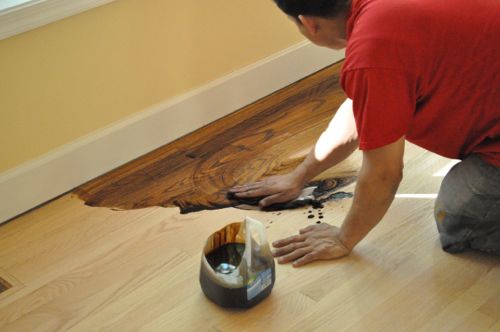
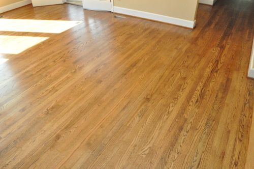
The stain only needs about 5 minutes to penetrate. After that, the guys wiped up the excess stain, wiping in the direction of the wood grain.
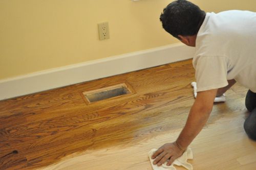
The guys worked in long, thin strips and quickly stained the wood floor.

At this point, any imperfections from sanding would be much more visible, and this would be the time to fix them. Danny and his crew didn’t find any problems.
The stain was dry in about 2-3 hours.
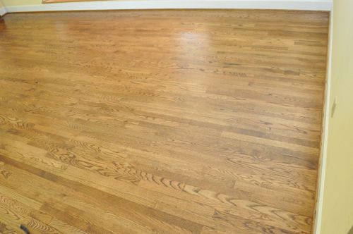
Step 11: Apply Shellac
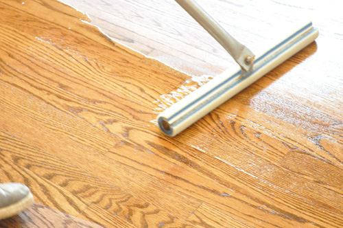
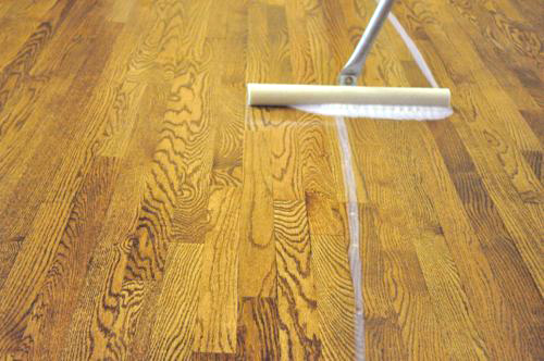
The guys applied a coating of shellac using floor coaters for the big open areas and trim pads for around the perimeter.
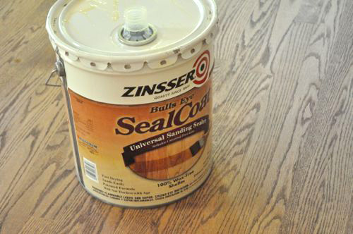
The shellac provides a seal coat that will dry hard and bond with the polyurethane.
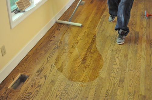
Again, the guys worked in thin, long section, taking care to apply the shellac evenly.
The shellac is dry after about 45 minutes.
Step 12: Apply Polyurethane
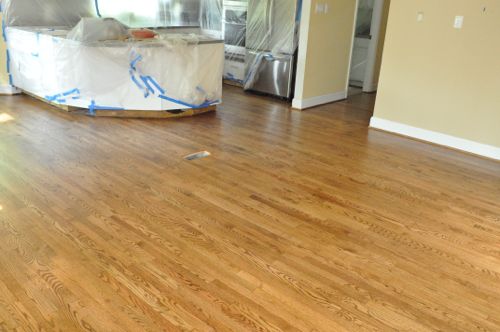
Next, Danny’s crew applied Bona Mega polyurethane with a satin finish.
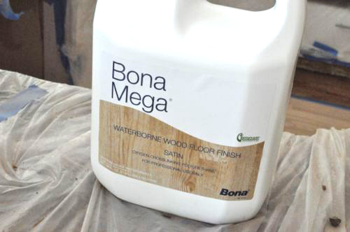
The polyurethane goes on much like the shellac, using the floor coater and trim pads. The guys applied two coats of Bona Mega, with about 3 hours of dry time in-between. This picture shows how they worked to maintain a wet edge and “snowplowed” the poly across the floor.
Step 13: Install Shoe Molding
After the poly was dry, the guys installed shoe molding to replace the molding that had been removed at the beginning of this job. The molding was stained and sealed just like the floor before it was installed.
Step 14: Apply Polyurethane Again
Before this last coat of poly, the guys used a screening disc and the floor buffer to abrade the floor for the smoothest results.
Pro-Talk: Screening discs are mesh screens with abrasive particles bonded to it, and they act much like sandpaper.
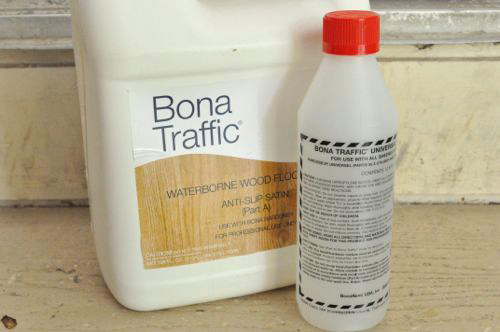
Danny’s crew applied one more coat of polyurethane, and this time they used Bona Traffic with an anti-slip component. Like the name implies, Bona Traffic is designed for high-traffic areas to provide an even more durable finish. It’s a two-part product, and once the hardener is added there’s a four hour work window. Bona Traffic is applied just like Bona Mega.
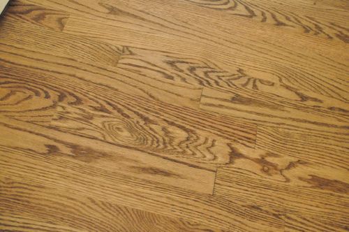
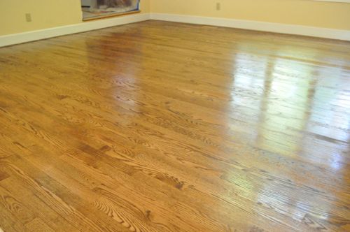
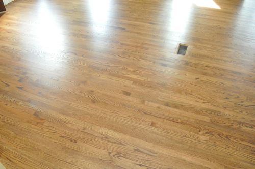
Finished
With the last coat of polyurethane applied, the floor is finished. It’ll take 7 days to reach full cure, and until that time the floor is susceptible to scuffing. Even so, the floor is ready for light foot traffic after about 24 hours.
Pro-Tip: Area rugs can slow the curing process and should not be replaced until after 7 days.

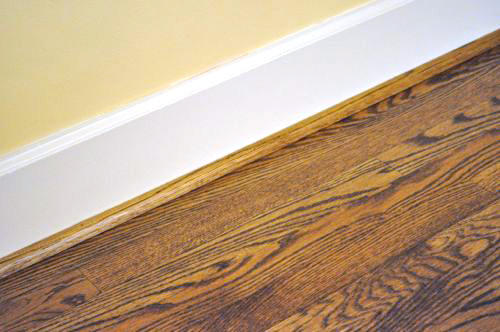
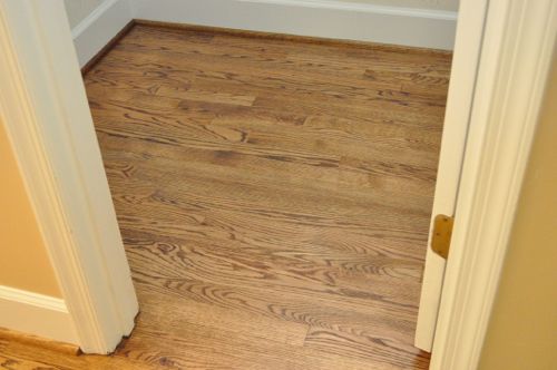
This is where the old and new floor meet, and even up close it’s very difficult to notice any transition.
Pro-Tip: Homeowners should change their furnace filter after refinishing is completed.
Interested in laying your own hardwood floor? Check out our Project Guide for Installing Hardwood Flooring to learn how.
If you’ve enjoyed this guide on how to refinish hardwood floors, give it a +1 and share it on Facebook! Thanks.
How to Paint an Epoxy Concrete Floor Coating (Quikrete Example)
January 13, 2017 | by Ethan (email) |Our garage workshop floor was in need of some serious TLC. We applied an epoxy garage floor coating to cover the ugly oil stains and give the shop a nice, polished look. I’m amazed at the difference the floor makes and would recommend an epoxy coating for anyone looking to class-up their garage, basement or other concrete surface. Read on to learn how we did it and a few tips to remember when you start this project.
Editors Note: A lot of readers have found this article helpful in transforming their own basement or garage. We hope you enjoy the article, and if there’s anything we missed, leave a comment. We’ll answer it as best we can ASAP. Please consider sharing this on Facebook and giving it a +1. Buttons can be found floating on the left side of your screen. Thanks!

Quikrete was kind enough to send us a few kits for this tutorial. I’m really impressed with the results and would recommend stopping by Lowe’s to pick up a set for your own garage.
Step 1: Clean and Prepare the Surface
The most important part of applying an epoxy coating is ensuring the concrete is sufficiently cleaned and porous. This is so critical because dirt, debris, oil, paint, and other junk can prevent the coating from adhering to the concrete slab. If that happens, your floor will delaminate and the coating will chip and flake. You’ll be disappointed, and re-coating will require significant additional steps. Take this step seriously. Make sure that the surface is clean and etched (meaning, not smooth).
These pictures show the garage floor before we started. You’ll notice plenty of oil stains from 25+ years of parked cars.


Address any cracks or other concrete damage before you start. The epoxy coating is thick and will completely fill small hairline cracks, but larger cracks will still be visible if you don’t patch them. Also, cracks provide a path for moisture, and that can cause the epoxy coating to “cloud” over.

We started the cleanup process by pulling everything out of the garage and sweeping it clean. Fred grabbed a garden edger and used it to scrape away dried drywall compound and anything else that he could remove.

I have a stiff bristle, scrubber brush with hose attachment, and it is the perfect product for cleaning a garage floor. It allowed me to wet the surface with a controlled spray and scrub the floor all in one tool.


One of the items included in the Quikrete kit is Bond-Lok. It’s an acid concentrate that you mix with water to clean, degrease and etch the concrete. You’ll make a 3:1 mixture, and each of these bottles is about enough to clean a one-car garage. You may consider purchasing an extra because you’ll need to apply Bond-Lok undiluted to any really tough stains. We found it was a good idea to apply Bond-Lok directly to oil stains and let it sit for about 5 minutes before scrubbing. You’ll know it’s working because it’ll fizz.


Your goal for cleaning the concrete is not to remove any evidence of a stain, but rather to ensure that it won’t prevent the coating from seeping into the pores of the concrete. For that same reason, it’s important to remove any sort of concrete sealer that was previously applied. This can be a very tedious task and, if the slab was sealed professionally, may require sanding or chemical stripping on a larger scale than most do-it-yourselfers would be comfortable with.

We allotted a full 24 hours for the concrete to dry before we continued to the next step. We recommend waiting at least 24 hours because a well-etched surface is likely to hold moisture in the pores of the concrete. If any water pools on top of the concrete, you absolutely cannot apply the epoxy coat. You must re-clean/degrease/etch this area until water does not pool.
Step 2: Paint the Epoxy Concrete Coating and Spread Flakes
To prepare the epoxy, we thoroughly mixed the two parts and let it sit for 30 minutes. Because of the delay, try to anticipate when you’ll need more and mix the next gallon before you run out. You have only 2.5 hours to apply the coating, so don’t get too far ahead, either. We found no issues with getting all three cans of epoxy applied in about 2 hours.


Applying the colored epoxy is much like painting a wall. You’ll use a brush to cut-in the borders and a 3/8
nap roller for the rest. The coating is very thick and painting it is slow going. I also noticed that the fumes can be pretty bad. Make sure to that wherever you’re working is well ventilated.

Since the color coating is so thick, roll in one direction, and then switch directions 90 degrees. This’ll help make sure everything is completely covered. Quikrete offers a lot of different colors, and we choose “Grayling.” You can see in the pictures that it dries darker than it goes on, so don’t be alarmed if it looks too light at initial application.


We worked in small sections because we opted to spread color flakes. The flakes are great because they hide any imperfections, and they add a bit of character to your floor. I love how they come “sealed for freshness”. We sprinkled the granite mix, which includes black, white and gray flakes.
Color Flake Tip #1: The flakes at the bottom of the can are much smaller. If you’re looking for a uniform distribution, mix up the can periodically so that you don’t end up with all the small flakes at the bottom poured on one area of the floor.
Color Flake Tip #2: The color flakes will sit “on top” of the epoxy. If you spread the color flakes, you’ll likely want to spread the optional clear coat on top of the floor, as described in Step 3.


Just like when laying tile, you need to plan an exit strategy and work your way out of the room. We opted to back out of the garage into the house, which worked just fine, even for two guys as large as us.

All together we needed almost three whole gallons to cover a deep, two-car garage. Even before the clear coat, this floor is looking awesome!


We waited another 24 hours before applying the clear coat epoxy to make sure everything was completely dry.
Step 3: Paint the Epoxy Clear Coat for a Glossy Shine
This third step is optional, and you can decide for yourself if it’s worthwhile. We decided to apply a clear epoxy coating for an added layer of protection and high-gloss finish. Applying the clear coat is very similar to painting the color coating. Just like before, you need to mix the two parts and let it sit for 30 minutes.
 Unlike the color coating, the clear epoxy looks white until it dries. This is intentional because it allows you to see where the clear coat is already applied.


Applying the clear coat goes fast. It’s not nearly as thick as the color coat, and it has way less fumes. We only needed two gallons of clear coat to cover the entire floor.

The white fades to clear pretty quickly. Even so, you need to give it another 24 hours before light traffic and 72 hours before parking a car.

After everything dries, you’re done! Now you’ve got a beautiful shop, garage, or basement floor that is protected from gas, oil, scuffs, etc. and it’s easy to clean. A concrete coating can really dress-up a space and give it a showroom feel. We love this floor in our workshop, and this project is simple enough that anyone can achieve great results.


If you’d like to learn more about what we’ve been doing to get our workshop ready, read about installing pegboard and starting to run painted conduit.
When I unveiled my amazing dust collection system a couple of months ago, I remembered Jeff speculating that a zero clearance insert (ZCI) on the table saw may further reduce the amount of dust that escapes, and I squirreled that idea away in the back of my head. Soon after building the custom spice rack for Jocie, Fred and Kim put in a request for me to build another one, and I decided it was time to buy a dado stack. What does all this have in common? I needed some new table saw inserts.
If you look around online, you’ll spend at least $20 on each blank insert. Instead, I chose to build my own inserts, and I started with a zero clearance insert. The key for any insert is to support the workpiece which reduces tear out and splintering. On a ZCI, you have the added benefit that smaller pieces can’t fall through.
Step 1: Remove the OEM Throat Plate
I have a Steel City table saw, and the throat plate is held in place with four powerful magnets.


Step 2: Trace Outline
I traced the outline of my throat plate onto spare 1/2″ plywood I had in the shop. If your throat plate is similar to mine (and I bet it is), the plywood will be just thinner than the original throat plate, and that’s a good thing.

I’m making multiple inserts to accommodate different blades and dado stacks even though I only plan on finishing one today.

I used my table saw and miter saw to cut the inserts roughly to size.
Step 3: Route with Bearing Bit
I was really confused the first time I saw a router bit with a bearing on the end, and I remember trying to take the bearing off. Eventually I learned that these bits are used to follow a template or pattern, and they are really useful for making table saw inserts.

By lining up the bearing with the OEM plate, I cut a perfect match in no time.


Step 4: Position Leveling Screws
I used a rubber mallet to make some indentations where the leveling screws were located.

Step 5: Begin Kerf Cut
Many table saws (mine included) can’t lower the blade far enough to fully seat the ZCI. To start the kerf cut, I replaced the OEM throat plate and clamped my blank overtop. I started the saw and slowly raised the blade.


Step 6: Continue Kerf Cut
After the cut was started, it was easy to set the ZCI in place and continue raising the table saw blade, using a piece of scrap to prevent it from coming out.

Many ZCI’s don’t provide anything in the way of splitter, riving knife or attachment for the blade guard. I decided to extend the kerf cut enough that my riving knife would fit too, and that enables me to use the blade guard as well.

Step 7: Adjust Fit
Originally, I didn’t think this step would be necessary. However, with a zero clearance insert, there’s no extra space, and I didn’t want the insert to move at all. Even on the OEM plate there is a very slight gap so to make my ZCI even more snug, I drove a few roofing nails into the edge. The same results can be achieved more elegantly with a set screw, but I found this to work just as well.

Step 8: Leveling Screws
This is another step that set screws would have come in handy. Again, I opted for my roofing nails to provide contact for the magnets and raise the insert flush with the table. I cut the nails to length with Linemen’s pliers and pre-drilled the holes.
My ZCI was a hair too high on one corner so I sanded that area until it was flush.

Step 9: Drill Pull Hole
Needless to say, it’s almost impossible to remove this insert without a small hole to grab it. The last thing I did was drill a pinky-sized hole off to the side.

How to Build a Deck (with 120+ Pics, Diagrams, Pro-Tips, & Helpful Links)
May 25, 2016 | by Ethan (email) |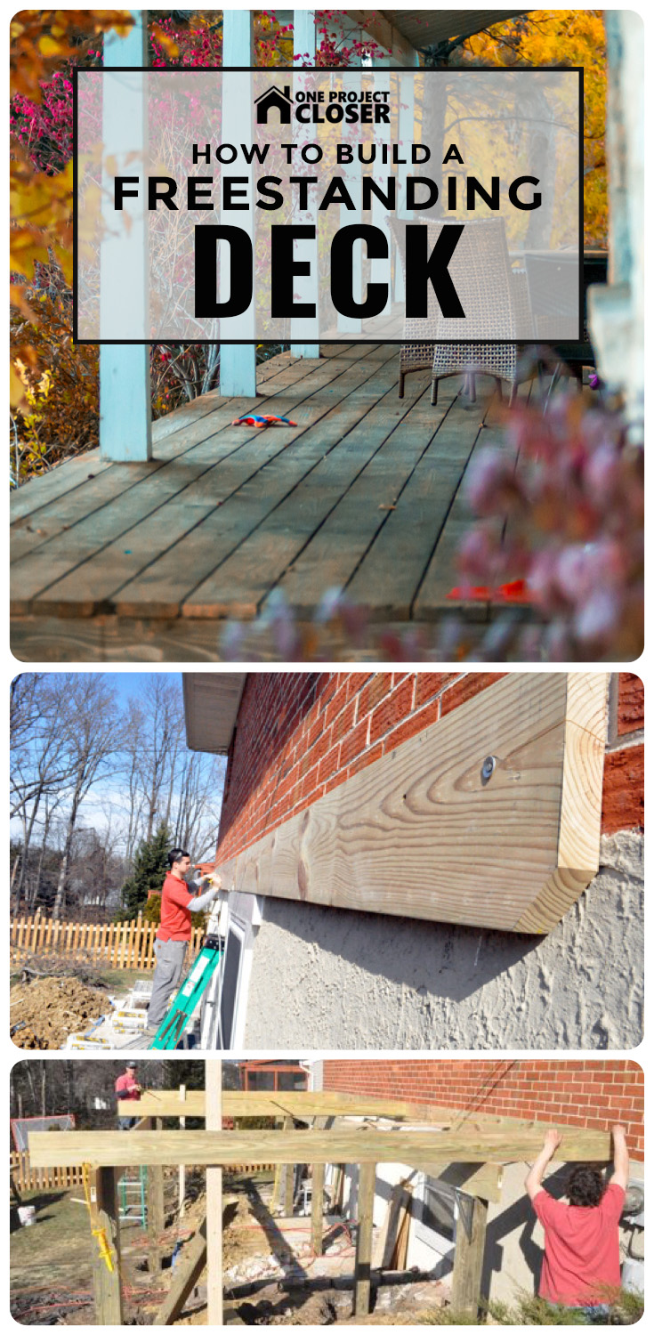
If you’re a regular reader, you know this detailed guide is the culmination of many days shadowing expert general contractor and carpenter Steve Wartman. I was on-site as he and his crew built this deck, taking pictures of the progress, documenting the work and discovering tips and tricks. I’m convinced that there’s no better way to learn how to tackle home improvement projects than following a licensed contractor through a build. If you enjoy this article, check out our other Project Guides. To stay current on all our Pro-Follows, subscribe via RSS or email.
If you live in the greater Baltimore area and are considering adding a deck to your home (or any other sort of home improvements), I suggest you give Steve a call. This article is a great example of the high quality and professionalism that Steve and his crew bring to every job. For more examples, check out our articles on building a shed or how to hang drywall.

How to Build a Freestanding, Composite Deck
The same homeowners that had Steve’s crew build a custom shed have contracted him again to construct a new, composite deck on the back of their home. They went with Trex brand composite materials for the build, because Trex is virtually maintenance free, meaning the homeowners won’t ever need to seal, brighten or strip the decking boards.
The Plan
Here’s Steve to give you a short introduction to this project.
Video Summary: Steve describes a plan to build a new, 12 x 24′ deck and a 4′ set of stairs. It’ll have two rows of buried posts, Trex composite decking, Trex trim boards and a white vinyl rail system.
Step 1: Plan, Dig and Pour the Footers
Determining the location of the deck was easy. It was more difficult to determine how many footers were required and where they were going to be located. This video shares some details about footer and ledger board requirements.
Video Summary: How the deck attaches to the house is one of the factors that determines the required number of deck posts and footers. Other considerations include the size and shape of your deck, how much weight it will hold, and the size of the beams. This deck is rectangular in shape, and the homeowners aren’t planning on adding a hot tub (or other heavy objects). Since Steve’s crew couldn’t through-bolt the ledger board, they’ve installed two rows of posts, creating a “free-standing deck.”
The first row of posts was placed 3′ off the house, and the second row of posts was 8′ after that. Posts are spaced no more than 8′ apart so that means we have four posts per row, with the first row having 1 additional post to account for the stairs. Here’s a sketch of the deck and posts.

After Steve determined the footer locations, the crew ran several string guides and started digging. This was no small task because they decided to cut through the brick patio and underlying concrete before learning it was 5-1/2″ thick.


Each footer needed to be deeper than the frost line, and here in Maryland that means footers must be at least 30″ deep. In areas such as northern Minnesota, footers need to be at least 60″ deep, so check the code for your area before digging. Steve’s crew dug each hole about 24″ across. Before continuing, all the footers needed to pass inspection. In this jurisdiction, this was the only required interim inspection, and the checklist includes:
- there are a sufficient number of footers to properly support the deck
- the footers are spaced appropriately
- the footers are dug to the proper depth (30″), which is the depth required to be below the frost line in this region
Pro-Tip: Before you start digging, have underground lines (water, gas, power, communication, etc.) located. Call the North America One Call Referral Service (1-888-258-0808). It’s free and required by law.


The inspection went smoothly, and Steve’s crew started pouring the footers. Using 80lb. bags, they mixed enough concrete to achieve an 8″ thick pad.


They used a garden hoe to make sure the concrete would set with a nice, flat surface.

Step 2: Install the Ledger Board
While the concrete cured, the guys started on the ledger board. They installed a 2 x 10′ ledger along the entire length of the deck, taking care to ensure it was completely level. Steve and his crew temporarily secured it in place using a powder charge nailer. Here’s a quick demonstration:
Video Summary: In the video, Steve shares how driving temporary anchors makes it easier to install the ledger board. For this brick and masonry house, you have to use concrete fasteners, and a powder charge gun actually uses a .22 caliber shot to quickly drive the anchor. It’s important to pre-drill a hole so you don’t split the board which also enables the nail to go further. That’s how they temporarily set their ledger board.
Next, the crew marked the locations of their joists. Often you’ll see joists spaced at 24″ on center (oc); however, with composite decking, joists need to be closer together. Steve’s crew marked their joists at 12″ oc. Predetermining the joist locations ensured that none of the concrete anchors will create an obstruction, and it allowed them to place an anchor in every bay (between each joist).


The crew used concrete anchors called Red Heads to secure the ledger board.

The concrete anchors needed to be staggered and, for the upper row, driven into the mortar between bricks. For each Red Head, the guys pre-drilled a hole, used a hammer to drive them in place, and a socket wrench to tighten them down.


Step 3: Install Deck Posts and Beams
The crew used pressure treated 6 x 6″ for posts on this deck. These were rated for “ground contact”, which, as you might expect, means they can be buried directly in the ground.
Pro-Tip: Pressure-treated lumber is infused with chemical and rated by the amount per cubic foot of wood. Ground-contact lumber has .40 pounds of preservative per cubic foot, and above-ground rated lumber has .25 pounds.
Pro-Tip: The size of posts required for a deck installation depends on the span being supported by the post, as well as the height of the deck. Steve’s crew prefers 6 x 6″ posts for their sturdiness; however, 4 x 4″s may be used in certain low-height installations. In certain very tall installations, cross-members may be required between the posts for added support and to prevent racking.

The challenges with installing deck posts include keeping each post:
- square with the house
- square with all other posts
- the right distance from the house
- notched at the proper height to support the beams and joists, ensuring an adequate slope away from the house
The crew moved the first post into place and marked a line indicating the very top of the post which was even with the support beam. The reference point on the ledger board was the bottom of the floor joists.

Using a circular saw, they cut the post to the proper height, based on the previous measurement.

Using a reciprocating saw, the crew cut a notch for the support beam so that the top of the post was flush with the support beam.

The support beams consisted of two, 2 x 10″ boards nailed (and later bolted) together, side-by-side in the notch.

Pro-Tip: You may see support beams where the deck post is sandwiched between two pieces of 2x material. The method we describe here is better, because when the two boards are touching, they act as a single unit. Furthermore, separating the 2x material requires additional blocking in between the joists to support bolting, and therefore, longer bolts.
With the post cut to the appropriate dimensions, the crew moved it into place, and secured it with temporary boards. This was a tedious activity that required several pairs of hands and repeated measurements, but it was extremely important for the finished product.

The crew repeated the process for the middle post, and, after it was in place, added one of the 2 x 10″s that will makeup the support beam. This allowed them to double-check level and distance from the house across the entire gap, and make adjustments as needed to each post.

Again, the level was aligned just like a floor joist so that the top of the floor joist sat flush with the top of the ledger.

This process continued for all five posts in the first row along the house. The middle post was where two support beams butted against each other. The transition was accomplished by equally dividing the space in the notch between the two beams.


In this picture, you can see all the temporary boards that kept the posts and support beam in place.

Once the crew was satisfied with the entire row, they back filled the dirt and tamped it down, taking care not to move the post. Any movement required additional measurements to ensure nothing moved out of square with the house or the other posts, and that the post was still at the proper height.


The second row of posts went in much the same fashion except for one thing. Since the crew had the ledger and first row finished, they added a few joists and ran a string guide to make it easier to setup the rest of the posts. It’s also important to note that they established a 3/8″ slope (over the entire width) to direct water away from the house.


Once the crew had set a few more posts, they ran a tape measure along the diagonals to check for square.

This picture shows a crew member adding that second 2 x 10″ to form the support beam.

These two beam components were later secured with staggered carriage bolts through the post.

Step 4: Install Floor Joists
Since the ledger was already marked, lining up the joists was not a difficult task.

Here you can see the crew once again made sure the joists were square to the ledger. The importance of re-checking square measurements cannot be overstated in a deck build. If components start out of square, it will be hard to make the deck look good at the end.

Pro-Tip: Joists should always be placed “crown up” in an installation. All joists must be oriented identically in this manner to ensure the deck won’t have waves between the joists. In our tutorial on How to Build a Shed, we provide a video on checking and marking dimension lumber to identify the crown.
The crew did break out a planer at one point because they found a few boards were thicker than the others.
Pro-Tip: Double-check board dimensions, because you may find some variation in your lumber package. Never assume that all joists are exactly the same dimensions. Purchasing extra lumber allows you to be more choosy and avoid using bark-cut or bowed boards.

Each joist was toe-nailed in place with four nails, and then a Simpson hanger tie was added.


It was fun to see the crew use this palm nailer for fastening the hanger ties. It made driving the 10 nails into the hanger very quick–much quicker than could be achieved with a regular hammer, which is an acceptable (albeit much slower) alternative.

The guys used Simpson nails with the hanger ties. The shorter nails (N10) secured the hanger to the ledger, while the longer nails (10d) were used for the angled slots. Using the correct nails for hanger ties is very important, as the strength of the hanger is dependent on using the appropriate hardware.

As you may remember, the crew planned the joist spacing at 12″ oc since they were installing a manufactured composite decking surface. For traditional 5/4 pressure treated wood surface deck, 16″ oc is more common. Joist spacing depends on both surface material as well as spanning distance between the posts.
Pro-Talk: The term “5/4 lumber” is shorthand for lumber that is nominally 1.25″ thick (or 5/4s of an inch). 5/4 lumber is actually finished to 1-1/16″. The type of 5/4 lumber used on decks has rounded edges and is known as “decking board”. Composite decking material is generally the same size as 5/4 lumber (or close to it).


Pro-Tip: Overhead power lines must have at least 10′ of clearance. These lines will later be buried to meet that requirement.
Step 5: Add the Band Board to the Joists
The crew got all the joists set in place and secured with joist hangers, including a double-joist in the middle. Since the deck was 24′ long, the band board consisted of two 2 x 8″s butted against each other, and the transition at the double joist.

Using a string guide, the guys marked the ends of each joist and cut away the excess with a circular saw.

The band board was situated between the rim joists and secured with four nails per joist. Note that the last joist was 1.5″ longer to remain flush with the band board. This allowed nailing from the side of the joist into the board.

Pro-Talk: A rim joist, or band board, is the final joist that caps the end of the row of joists that support a floor.
Step 6: Install Blocking Between the Joists
Blocking in between the joists provided a surface to mount the rail system. This was especially important because they planned to “picture frame” the perimeter to conceal the cut ends of the composite deck boards. To achieve this, the crew cut pieces of 2 x 4″ to fit in between joists and sistered a 2 x 4″ along each rim joist.


Step 7: Build the Stairs
Building the stairs was not an overly difficult process; the key to success was making accurate cuts. In this short video, Steve shares how he calculated the stair stringer dimensions.
Video Summary: Steve describes how he started the process to build the stairs by first determining the total height of the stairs. Stair risers need to be between 7 and 7-3/4″ tall, and using 7-1/2″ translates into 12 risers. Likewise, stair treads need to be between 10 and 11-1/4″ wide. Since they will have 12 steps, the tread needs to be 10-1/2″ with a 3/4″ overhang. If this still seems confusing, Todd from Home Construction Improvement has a very simple Stair Stringer Calculator spreadsheet you can download for free.
With the rise and run dimensions calculated, it was time to mark the stringer. Watch this short video for more information about marking the 2 x 12″.
Video Summary: This video shows how to scribe the stair stringers. It’s important to check the crown of the board and make sure it’s “crown up.” Using a framing square, line up the rise and run measurements on the edge of the stringer and mark your line. Then you move down and repeat the process. Lastly, extend the first line (riser) through the 2 x 12″ and cut off the excess.
I put together these diagrams to help visualize the stringers. You’ll notice that the very last step is 1″ shorter. That’s because there are no deck boards on the concrete, and shortening that riser keeps each step height consistent.


The stairs measured 4′ across and to maintain the 12″ oc supports they will needed a total of five stringers.

The two outside stringers were slightly longer so that the cross member was situated in-between them. The inside stringers butted up against the cross-member, and this was important because it allowed Steve’s crew to drive nails in two dimensions for a more secure hold.


These pictures show how the guys assembled the stairs.


In the diagram above you see mention of a concrete pad. It’s important to have something solid at the bottom so the stairs don’t just sit on the ground which will erode over time. While building the stairs, the guys also built a concrete form and poured a small concrete pad.

This pad had two “footers” where the stair rail posts will be situated.


Here are a couple of shots showing the stair landing. It measured approximately 4 x 4′, and the joists and band board were installed just like the rest of the deck.


After the concrete cured, they moved the stairs into place with the top of the stairs resting on the deck support beam.


Steve’s crew checked that the stringers were level and then nailed them in place.


Step 8: Flash the Ledger Board
Contractors use flashing to prevent water and moisture from finding their way into a home. The general idea is that since water flows down with gravity, you can overlap waterproof membranes (like siding, stucco, metal flashing etc.) that will direct water away from the house. Improperly flashed decks can cause a lot of problems, because leaks may not be visible right away, and they are not always readily diagnosed. Furthermore, making repairs after a deck is finished can be a very onerous task. (Although some deck construction methods make it easier to address such challenges than others. We talk about that below.)
The Unique Situation with this Deck: The exterior of the house is a combination of brick and block. The ledger board was fastened to the brick, which is already constantly exchanging moisture with the outside world. Since the masonry anchors Steve used did not penetrate deep enough into the brick to disrupt the moisture barrier, Steve’s crew was confident that this deck did not require separate flashing. (There is no path for water to enter the home.) Typically, the crew would err on the safe side and flash anyway; however, in this installation flashing would have been visible and would have detracted from the look of the finished product.
This situation with this deck is unique because the ledger board in this design was not a load bearing element. This deck is freestanding, with two sets of posts and beams on which the joists sit. In most decks, the ledger board is load bearing, and the bolts go all the way through the rim joist of the house. This situation always requires flashing to prevent leaks, and it’s recommended that holes drilled for bolts should be filled with a silicone sealant. Look for helpful links including 2012 International Building Code (IBC) and International Residential Code (IRC) in our Related Content section at the end of the post.
If the crew had decided to flash the deck, here’s how they would have done it:
- Trench out one of the horizontal mortar joints above the ledger board enough to insert an inch of copper flashing.
- Before inserting the flashing, bend a small double-back hem that will act as a wedge between the bricks.
- After inserting the flashing, seal the joint with a flexible sealant.
- Make sure the flashing extends down over the ledger board.
- Cut the flashing at each floor joist in order to get the flashing between joists to bend.
Pro-Tip: Newer chemicals for pressure treated wood like alkaline copper quaternary (ACQ) and copper azole, are more corrosive, and aluminum flashing and steel z flashing actually deteriorate when in constant contact. For that reason, use a rubber or copper flashing product. One reader also suggests using 1.5″ wide strips of #15 building paper between the two can also prevent problems.
Step 9: Lay the Composite Deck Boards
Steve’s crew installed Trex Transcend composite decking boards for this build. The homeowners were really excited about this, because composite decking is almost completely maintenance free. They won’t ever have to worry about sealing, stripping or brightening the boards. The band board and stair risers will be wrapped in a white, Trex composite trim.

Trex is a capped-stock, which means the core of the board is composed of a different material. For that reason, exposed ends are especially undesirable, and Steve’s crew created a “picture frame” around the perimeter to conceal the board ends.

The guys knew that the house wall was not 100% straight so they ripped the first piece of Trex in such a way as to eliminate as much inconsistency as possible.

They cut a 22.5° scarf joint to conceal the transition from one board to the next.
Pro-Talk: A scarf joint is made by overlapping two pieces of wood along a tapered, beveled, or chamfered end.


Steve’s crew used screws designed for composite decking. If you look closely, you’ll notice that the top is reverse threaded which holds the screw in place while the screw-head acts as more of a plug.


Screwing down the deck boards was slow going because each screw needed to be pre-drilled to prevent the board from becoming disfigured. Besides the added cost of materials themselves, this step made the installation of composite decking more expensive than the installation of traditional pressure treated products.

After the guys set two adjacent pieces of the “picture frame” in place, they started laying the diagonal boards. It was important that the first board be laid accurately, because they acted as a point of reference for all of the others.

Steve’s crew cuts the end at a 45° and measured the opposite side to ensure the angle stays true.

Each board was secured with two screws at every joist.

Pro-Tip: You can opt for hidden fasteners that are driven into the side (rather than the face) of the deck boards. This requires a specialized jig and incurs some extra cost.
All decking (composite and traditional) will expand and contract with changes in weather, and it’s important to adequately space each board to provide that necessary room. To achieve a uniform spacing, Steve’s crew sets up a block with 8d nails to create the gap.

This picture shows the progress after a few rows have been laid.
Pro-Tip: Trex composite features a wood-grain inlay to make the boards look more like a natural product. The wood grain is a pattern that you’ll see repeated many times over the length of a single board, and if you’re not careful to stagger the pattern, it will be readily apparent to anyone looking at the deck.

After the diagonal boards were in place, these ends were trimmed with a circular saw.

Pro-Tip: Even though I describe this as a 12 x 24′ deck, it will actually measure a few inches shy of 12′. If the homeowners had truly wanted a 12′ deck, it would require Steve to purchase 20′ composite boards since they’re being installed diagonally, and that jumps the price up significantly. By making the deck just a little shorter, Steve can purchase 16′ composite boards and provide a more cost-effective solution.
Here are some images that show how the deck progressed.


They snapped a chalk to mark their line for the circular saw.


Step 10: Install Trim on the Band Board and Stair Stringers
Steve’s crew installed a white, 2 x 12″ PVC trim board on the outside stair stringers and the band board. It gave the deck a nice, polished look and matched the rail system. PVC is nice to work with because it’s lightweight, flexible and maintenance free. The guys mitered all the corners and used finish nails to fasten the boards.


They filled all the nail holes with a PVC putty so that you can’t even see the nail hole.

To cut the PVC to match the stair stringers, they cut the very first riser and temporarily tacked the PVC against the stringer for marking cut lines. This was better than re-drawing the stringers because even the most accurate carpenter may have some variation, and this ensured that each section matched perfectly.
Editors Note: We are walking through this deck build chronologically, but stair stringer trim is best left after the treads, risers and stair guards have been installed.


PVC is easy to cut, so a jigsaw makes short work of cutting out the stringer trim.


Step 11: Add Stair Treads and Risers
After getting the trim in place, the guys moved onto the stair treads and risers. Every three or four steps, they added blocking to ensure a consistent width.

Steve’s crew also added these blocks at the base, which will have concrete anchors driven into the small slab below. The two outside bays don’t have blocks because they’ll have stair posts (eventually).

Starting at the top, the crew measured the riser first, cutting a piece of PVC long enough to reach across the cut edges of the stringer trim.


Next, the crew cut the first tread. You can see how that the tread does not extend the entire length. This is on purpose, because the crew left room for a return piece to conceal the cut edges of the tread.

This picture shows one of the return pieces that hasn’t been fasten yet. It was slow going to get all the cuts exactly right. To help themselves out, the guys put together templates. The return pieces were secured with screws through the side of the return and into the tread board.

Another small detail that you might have missed is that the guys notched out the stair riser for the return piece using a Bosch multi-tool. This notching makes the tread appear to go under the riser when viewed from the side, which creates a nice visual look on the staircase.


Step 12: Install the Composite Rail System
Steve’s crew installed a white, vinyl rail system, and the picture below shows one of the steel posts and plastic spacers.

Remember the blocking between joists around the perimeter of the deck? That blocking allowed Steve’s crew to securely fasten the steel posts with 3-5/8″ LedgerLOKs. Each post was leveled as necessary with shims, ensuring it was perfectly vertical before fastening. After the LedgerLOKs were installed, each post got a plastic spacer which serves as a guide for the PVC trim cover.
Pro-Tip: The International Residential Code (IRC) requires rails to resist a load of 200 pounds.


Next, the guys trimmed the vinyl sleeve to the appropriate height and slipped it in place with another plastic spacer at the top. They placed posts about every 6′.
Pro-Tip: Deck railings are required to be at least 36″ tall.


Here’s a picture of one of the post caps. These were installed last and are usually glued in place to avoid using fasteners.

After the posts were set, the guys slid a square, base trim piece over the vinyl sleeve to conceal the bottom of the steel post. Next, they cut the lower rail to length and screwed it in place. It’s important to cut an equal amount from both sides of the rails to maintain a balanced appearance for the pickets.
Pro-Tip: The lower rail should be low enough that a 4″ sphere cannot fit underneath the rail.


This rail system had convenient mounting brackets for the upper and lower rails which included plugs and caps to conceal the screw heads. After the lower rail was fastened, they inserted a picket into each hole.

The upper rail was installed in a similar fashion, except for one additional step. The upper rail had an aluminum channel for increased strength, and Steve’s crew needed to trim this channel to length.


The guys placed 4 x 4″ pressure treated posts at the bottom and middle of the stairs. The set at the bottom rested on the concrete pad and were through-bolted in place.

The middle set ran all the way into the ground where they were secured much like the deck posts: a 30″ deep hole, concrete footer, and backfilled with dirt. They also through-bolted these and had to notch the stair treads.


Each post was cut at 36″ and a vinyl sleeve was fit overtop.

The stair kit had angled brackets. However, the guys needed to cut the hole for the picket.


Steve’s crew cut the upper and lower rails at a 35° angle, and trimmed them to length with equal portions cut from both sides to maintain an even appearance. The holes on the upper and lower rails were slightly bigger to allow the pickets to stand plumb.


Code requires a continuous handrail so they added this metal-core rail on the right side to meet that need.


Final Pictures
Here are several pictures of the finished product. This deck looks fantastic, and will be excellent for entertaining and enjoying the outdoors.


Special thanks to readers Jeff Williams, Icarus, Haus356, William, MissFixIt, Joe, Jake, Eek565, JD, Reuben Collins, Simon, and John. Without great questions and comments, this how-to wouldn’t be nearly as complete.
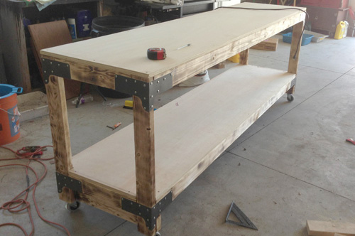
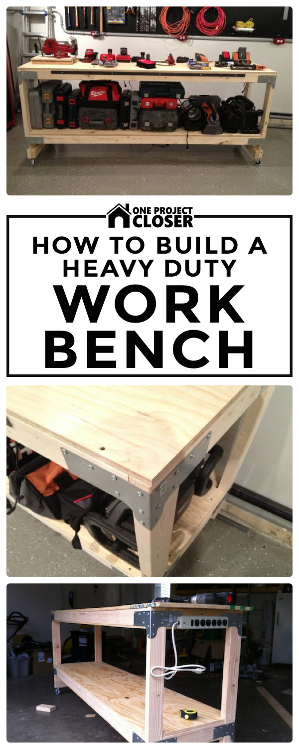
This weekend we built the first of four heavy duty workbenches for the OPC workshop! This project was very simple, and the design works not only for a workbench (as we’re using it), but also for sturdy storage shelves in a basement or garage. We built a two-shelf bench, but this design can be easily modified for three or four-shelf models.

Our goal for each workbench is an inexpensive, free-standing, movable table that can support a lot of weight (400+ lbs. total), with no perceptible deflection along the entire 8′ length of the upper shelf. We intend to use the lower shelf for tool storage (where deflection issues are less important), and the upper shelf for a combination of storage and work space (where deflection issues are more important).
All of the materials for this table came from our local Home Depot, and we spent a little over $120 total. After getting everything to the shop, it took about three hours to cut the wood and assemble the parts.

Design Overview: The general plan for this workbench is to create a reinforced frame of 2×4’s with a lower and upper plywood shelf. This might not sound very original, but I’d challenge you to find a sturdier design at this price point. The directions we provide build a workbench with a shelf measuring 2′ wide x 8′ long x 40″ tall. We strongly suggest keeping the width and length the same, because then you’ll need only one sheet of plywood, and you’ll minimize the number of cuts.
Materials List
Here’s the shopping list. All the materials can be found at your local home improvement center.
- (1) sheet of 3/4″ sanded plywood
- (9) 2×4’s
- (8) Simpson rigid tie connectors (see below)
- (200 count) #8 x 1-1/4″ screws
- (4 count) 3″ screws (see below)
- (2) 6′ flat, iron bar (see below)
- (1) tube of heavy-duty construction adhesive
- (4) 3″ locking casters (150 lb.+ rating per caster recommended)
Plywood: We chose cabinet grade 3/4″ plywood for the surface. Remember, 3/4″ plywood is actually 23/32″ thick, and that’s how it’s listed in the store. Cabinet grade plywood provides a relatively smooth surface that will be mostly free of splinters. At 3/4″ thick, it will easily absorb deflection over a 12″ wide span. Look for a sheet of plywood with no damage or marring.


We also decided to let Home Depot rip the sheet using their panel saw rather than cutting it ourselves. In our area, both Lowe’s and Home Depot will cut a sheet of plywood twice per sheet, free of charge.

Simpson Ties: Simpson ties are usually found in the metal building brackets rack. These rigid tie connectors are used to secure two wood members (forming a 90° corner) to a vertical post. If that sounds confusing, just imagine three 2×4’s intersecting to form a corner.


Screws: Make sure the screws you select have a large, flat head that will sit tightly against the Simpson ties without going through the pre-drilled holes. These Simpson ties are designed for #8 screws, which were sold in a rack right next to the ties.
Flat Iron Bar: The flat, iron bar is a thick strap measuring approximately 6′ long x 1″ wide. We used two bars on the top shelf to improve the horizontal rigidity of our workbench. It can be found with other pieces of angle iron at most home improvement centers.
Tools
- Drill/driver
- Impact driver (if not available, a drill/driver will suffice)
- Metal drill bit (for drilling the reinforcing strap. If no straps are used, this isn’t required)
- Miter saw (preferable for cutting 2x4s, although a hand saw or circular saw would also work)
- Jigsaw (or a hand saw)
Step 1: Cut the Lumber to Length
Like I mentioned, we had a Home Depot associate rip the plywood sheet in half lengthwise, creating two 2′ x 8′ pieces. Almost all of the remaining cuts involve trimming 2×4’s to the appropriate length.
Here are the 2×4 lengths you’ll need:
- (5) 93″ for the lengthwise supports
- (4) 17″ for the width-wise supports
- (4) 36″ for the legs
- (2) 24″ for the caster supports

Tip (Updated 1/15/2012): We’ve begun building workbenches for specific tools (like our miter saw), and we have adjusted the leg height so that the top of miter saw cutting surface perfectly matches our other workbenches. This is beneficial because now any of our workbenches can act as an infeed or outfeed support. For this an other workbench ideas, check out our four workbench mod suggestions.

Step 2: Add Reinforcing Iron Supports
Our biggest complaint with many DIY workbenches is their limited vertical rigidity. Most other workbenches will sag in the middle, because it’s difficult to support an 8′ span without some deflection. Furthermore, adding extra width-wise members does not increase vertical support over the entire length. To address this problem, we used the flat, iron bars to reinforce two of the lengthwise 2×4’s.

Using a metal drill bit, we drilled five pilot holes through the iron.

Next, we put down a bead of Liquid Nails adhesive.

We followed that up with five screws, keeping the iron flush with the edge.

Step 3: Build the Workbench Frame
It’s time to start assembling the frame, and we began with the workbench top (rather than the shelf). Placing a Simpson tie at each corner, we used an impact driver to put in the screws. If you find the 2×4’s are bowed, put them in crown-side up (meaning, arched down). It’s helpful to use a scrap piece of 2×4 to ensure that adjacent pieces line up at the same height.

You can see in the picture below that the table legs come all the way up even with the top of the adjacent 2×4 supports. This is important. If they are not aligned, your dimensions will be wrong, and the corners will be weaker.

We secured another lengthwise support down the middle of the workbench (12″ on center). We put two 3″ screws on each end to hold it in place.

Step 4: Build the Shelf Frame
We constructed the shelf in a very similar fashion using Simpson ties at all four corners. We flipped the table upside-down to slide the ties on, and then positioned them 7″ up the leg. The location is flexible, but they all should be kept consistent. One difference between the lower shelf and upper shelf is that we didn’t use the iron or the extra support member on the lower shelf. This shelf will be plenty strong, and we weren’t concerned with a little bit of deflection here.


Use the remaining lengthwise and width-wise supports to build the shelf frame.
Step 5: Cut the Shelf Corners
The plywood shelf needs to have notches cut from each corner to account for the table legs. Grab a scrap piece of 2×4 and trace the outline, being careful to orient it correctly. Use a jigsaw to cut them out.


Step 6: Screw Down the Plywood
Slide the shelf in place and put screws around the perimeter every 20″ or so. Countersink the screws below the surface to prevent things getting snagged on them. Do the same for the workbench top, and remember to put screws in the middle support as well. You may find that you’ll need to wrack the frame a bit to keep everything square and all the edges lined up.

Tip: We’ve incorporated some reader feedback and found that creating torsion boxes further improves the rigidity of the top shelf. This is an easy addition because all it involves is gluing and screwing another piece of plywood to the underside of the top shelf. To see more pictures and information, check out our update with four workbench modifications.

Step 7: Caster Supports and Casters
We wanted to install casters so that our workbench could move about the shop as necessary. We found 3″, locking casters that were rated for 110 lbs each (440 lbs combined). Screwing them into the end-grain of the table legs doesn’t provide the best hold so we added a cross member between the two legs.


The Finished Product
We’re really pleased with the finished product; the workbench top feels very solid. Even with a couple of hundred pounds on the surface, we didn’t notice any sagging. It’ll be a great surface for future projects, and the shelf is already getting loaded up.


For additional ideas about building shelves, check out our other article describing how we built shed storage shelves.
Reader Workbenches
We’ve had a significant number of readers let us know that they’ve built workbenches from our design, and they all love ’em! If anyone else has built (or is planning on building) one of these workbenches, we hope you’ll send in pictures so that we can feature them here.
From Todd B.
I just finished and this workbench is awesome. It is super sturdy and rugged. Thanks for the idea! This thing will last forever.


From Ryan M.


From Mark S.
This is probably one of many but I really enjoyed the design you created.
I needed a custom size for my motorcycle shed to allow for a lift between the workbenches. I decided to go with 4×4 supports so used the Simpson Strong-ties to fit that, then I had a local powder coating shop color them gloss black. I also used the Simpson post base (that comes in black already) so I could anchor the bench to the floor if I wanted.

From Kyle D.
I built the bench from the design from above. I love it. Very strong and mobile. Perfect fit for my garage.


From Matt D.
I love the wheels, great to be able to move it to the middle of the garage when using it for big projects and put it aside when not in use.

From Jared
“Used your plans with a little modification to build my workbench. Added a 12 plug strip to the underside, and gave the brackets a coat of paint before starting.”
Pin for later
Enjoyed this tutorial but want to reference it for later? Pin this image and share with with your friends also. THANK YOU!
How to Build a Shed (with a Record 100+ Pics, Vids, and Diagrams!)
May 22, 2014 | by Ethan (email) |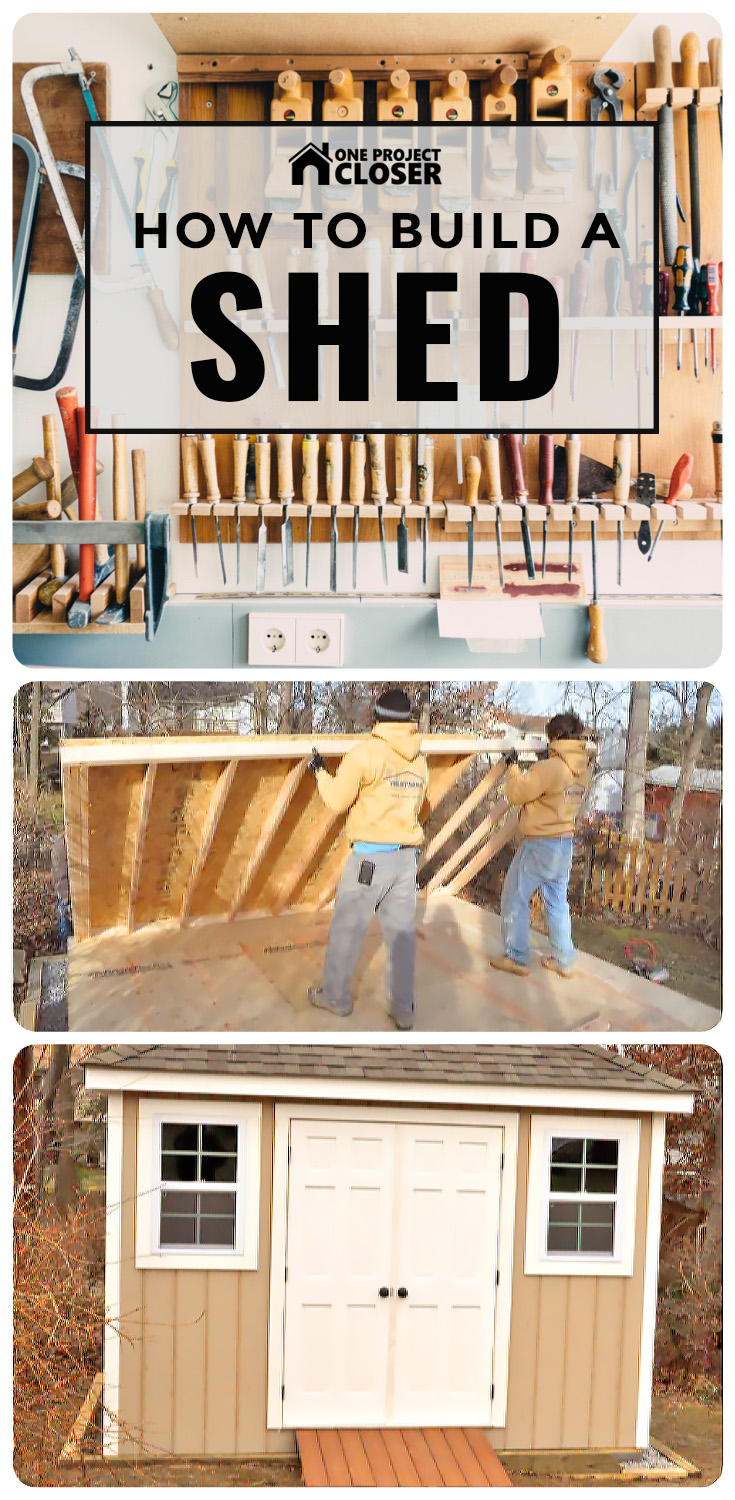
This article on How to Build a Shed is part of our library of DIY and expert Project Guides that share step-by-step explanations for a wide range of home improvement projects. As part of building this library, I follow expert contractors to the job site, documenting their steps, tips, techniques, and tools. We’re striving to be the best on the web! If you like what you read, please subscribe to our feed to keep up with all of the latest projects!
Most of last week, I followed expert general contractor and carpenter Steve Wartman and his crew as they built this great looking backyard shed. This article covers all of the details for building the shed’s foundation and subfloor, framing its walls, constructing a hip roof, installing a double door and windows, adding siding, laying shingle, and much more. Below the step-by-step instructions you’ll find a cost comparison for building vs. buying a shed, as well as additional resources for your own shed project.
If you’re looking for a contractor in the greater Baltimore area, I suggest you give Steve a call. He brings over 25 years of knowledge and experience, and this article is a great example of the quality of work he and his crew perform. To see more of Steve’s work, check out our article for building a deck and installing drywall.


Introduction
Most homeowners that want a backyard shed will have one built off-site and delivered to their home. (Here’s a video of a typical pre-built shed delivery we filmed in Fred and Kim’s backyard.) Unfortunately, shed delivery is not an option for all homeowners, and a common barrier is inadequate access. That’s why Steve and his crew were hired to build this shed. I’ll let him introduce the project.
Video Summary: The plan is to build a 10’x12′ shed. The homeowners are preparing to add an in-law suite to the back of their home, and this shed will provide storage for outdoor furniture and lawn equipment. The shed is deliberately planned for 120 sq. ft. because this is the maximum sized shed you can build in this area without pulling structural building permits. This shed will feature a foundation of solid, concrete block pillars, 2×4 framing, a hip roof that match’s the house’s roof design, and architectural shingles.
Step 1: Prepare the Site and Build the Foundation
After determining a location for a shed, it’s important to give it a solid, level foundation that will properly handle rain and moisture. Steve’s team accomplished this by digging out a 10’x12′ area with an additional 8″ of clearance on all sides. They lined the perimeter with pressure-treated 4x6s, sometimes going as many as three rows deep to handle a slight slope in the landscape. The crew used 20″ rebar to secure it to the ground, and 10″ Timberlok heavy-duty, wood screws to pull all the boards tight.


Pro-Tip: Timberlok 10″ wood screws should be installed through the face of one board into the end grain of the next (for all boards), and then down the top board through two or three boards.


The crew was able to reuse some of the excavated dirt to fill in low areas, being careful to tamp everything down to eliminate voids. They made ten foundation columns by stacking concrete blocks on undisturbed ground. Each column is composed of three solid 4″ blocks, glued to each other with construction adhesive. Using a line level, they ensured that all of the foundations were the same height, level, and equally spaced around the perimeter.
Pro-Tip: Foundation columns must be built on undisturbed ground. This is vital because undisturbed ground will not shift (potentially creating structural instability). Tamped dirt is not a reliable substrate for setting these columns, so care must be used when digging out the area.
Pro-Tip: Pouring a concrete slab foundation is a viable alternative to this method; however, it introduces additional concerns, such as frost heaving in colder areas. The shed design would also need to change to incorporate a 4×4 pressure-treated skid under the floor joists to allow rain and moisture to escape. The foundation design we present addresses these concerns, and is more cost effective than pouring a pad.
(See also: How to Pour a Solid Concrete Shed Base)
The crew filled in the perimeter with 2-4 inches of crushed rock. This provides a path for water to escape so that moisture doesn’t accumulate underneath the shed. It also looks nice in the finished product.

Step 2: Build the Outer Band Board
This shed features double band board construction, which means the perimeter of the bottom frame comprises a double ring of pressure treated 2×6 boards. The additional ring is helpful, because it adds to the structural integrity of the shed and provides a wider nailing surface for securing the walls to the floor.
For a 10′ x 12′ shed, the outer band board length and width should be 10′ x 12′, which is the full size of the shed. The inner band board (described in Step 3) fits inside this frame, and must be 3″ shorter in both dimensions (9’9″ x 11’9″) to fit snugly.
Step 3: Build The Inner Band Board and Floor Joists
The inner band board is constructed with joists spanning the shed’s width (front to back). The crew secures these joists with Simpson joist hanger ties and nails through the face of the band board. The joists are 2x6s placed 16″ on center (oc). Use of hanger ties and face nailing provides the necessary strength to hold the full weight of the shed and its contents.
Pro-Tip: It’s important to check the band boards for square by measuring both diagonals (corner to opposite corner). If they measure the same, the structure is square. If not, you must rack the frame to get to square before fastening the inner and outer band boards together.
Pro-Tip: We recommend a pneumatic framing nailer to install nails through the band board into the grain of the joist. This can be accomplished by hand (i.e., with a hammer), but would be far more time consuming.


This inner structure fits snuggly inside the outer band board frame.

The crew nailed the double band boards together, but not before confirming that everything was still square.

Step 4: Install the Subfloor
Steve is a big fan of Advantech flooring for its superior weather resistance. Using Advantech results in less warping, twisting and delaminating than would be present if traditional plywood or OSB were employed. If you check Advantech’s Website, you’ll see that they claim the lowest water absorption rates in the industry.
Pro-Tip: Fir plywood is a suitable alternative to Advantech if Advantech is not available. It is priced similarly.

Steve’s crew oriented the subfloor to keep the groove side exposed for the next row. This is important because it allowed the crew to setup a “beater block” to drive each sheet snug without damaging the tongue.

Next, the crew screwed the subfloor in place, taking care not to drive screws too close to the groove and create an obstruction for the next sheet.
Pro-Tip: Typical 2″, #8 screws are appropriate for this job. Screws should be driven every 12″ along the joists and the perimeter.
Pro-Tip: We recommend keeping screws six inches back from the groove until the next sheet is installed. If you install the screws too close to the edge before installing the next sheet, the next sheet will be VERY hard to get into place.
(See also: Installing a Plywood Subfloor in a Habitat Home)

The crew staggered the joints for each row and marked the location of the joists to enable easy fastening.
Pro-Tip: Plywood joints should be staggered lengthwise. This reduces potential floor bowing in the final installation.


Step 5: Frame the Walls
Pro-Tip: Dimensional lumber is often curved or bowed. Before you begin framing, it’s important to check each piece for warping, and if necessary, orient them all identically. In this video, Steve shares some pro tips for checking and marking boards.
This shed features 2×4 framing with studs placed 16″ on center. The crew framed the front wall first. This wall was the most complicated, because the front wall includes the door and two windows.
To frame the front wall, Steve’s crew began by measuring stud locations on the top and bottom plates. For this step, it’s useful to understand a bit of stud vernacular:
- King Studs or Common Studs: Span from the top plate to the bottom plate (the full height of the wall).
- Jack Studs: Support headers, which span above doors and windows.
- Cripple Studs: Used above or below windows and doors.
Pro-Tip: Many lesser quality sheds are constructed with 2×3″ boards at 24″ on center to meet a lower price point. Beware of this type of construction, as it is much more likely to result in bowed walls.
In this picture, the king stud locations are marked with X’s, and the jack stud location is marked with a J. Placing three king studs on the end isn’t necessary (you could get away with only two); however, the third stud provides a nailing surface on the inside corner of the finished shed, which is especially helpful for building shelves at a later date.

Headers are required above doors and windows, since these elements of a structure cannot support load. Typically, headers are made by sandwiching 1/2″ plywood between 2x material, resulting in a flush surface inside and out. In this case, Steve’s crew omitted the 1/2″ plywood because the inside will not be a finished space and does not need to be flush.
Pro-Talk: What’s 2x Material? 2x (spoken “two by”) refers to any dimension lumber that is nominally 2″ wide, such as 2x4s and 2x6s.
Understanding Header Math: Finished 2x material is actually 1.5 inches wide. Accordingly, placing two pieces of 2x side-by-side will give you 3″ of width. By sandwiching 1/2″ plywood between the boards, you achieve a 3.5″ width, which is the width of a 2×4. Depending on the distance being spanned and the load being supported, 2×6, 2×8, 2×10, or even 2×12 material may be appropriate. For the spanning distances in this shed, 2×6 header material is appropriate. For heavy loads (such as supporting a second floor), LVL or steel I-Beams are used for headers.


Just like installing the joists, keeping everything square was a big focus. After each wall was built, the crew measured the diagonals and made adjustments as necessary. The picture below shows the front wall after they finished framing. You can see the headers above the windows and door.

The other three walls were framed with studs placed 16″ o.c. without any other components.
Pro-Tip: A utility bar (like the Stanely FatMax Xtreme) is a useful tool for bending and torquing boards into place.

Step 6: Install SmartSide Panels
After each wall was framed, Steve’s crew installed SmartSide engineered panels. These panels are already primed, and they will be painted to match the house at a later date. These panels are a durable and relatively inexpensive alternative to other siding materials, such as vinyl siding.

The crew stapled the panels (rather than nailing them), because stapling provides a better hold.

Each piece overlaps the adjacent piece, and the top and the bottom of the panel extends beyond the wall to cover the top plate (above) and the band board (below).
In this picture, you can see the crew checking the spacing with a spare piece of 2×4.

Step 7: Frame the Hip Roof
This shed features a hip roof, which matches the roof on the existing home. Hip roofs are much more interesting than the more typical gable roof, and they are also much more complicated to build. Here’s a quick video describing the challenges of building a hip roof.
Fun Fact: Hip roofs experience lower wind resistance than gable roofs because each side is sloped.
Hip Roof Nomenclature
Hip roof terminology can be a little confusing, so I’ve put together this rough diagram showing the different components of a hip roof from above.

- Ridge rafter
- Common rafters
- Hip rafters
- Creeper rafters (also called Jack rafters)
- Top plate
The difficulty in building a hip roof lies in making all the required compound cuts. Steve explains a bit more about that in this video.
Build the Hip Roof
Rather than framing the walls and building the hip roof on top of the structure, Steve elected to frame the roof on the ground. It’s a trade-off, because while it’s easier to frame the roof on the ground, it can be challenging to get the roof in place afterward. This method is only possible when the crew is careful to keep the subfloor, walls, and roof perfectly square. Otherwise, the structure will be skewed and the roof will be misaligned.
As Steve mentioned in the video, he began cutting the rafters while the other crew members worked on the walls. This roof features a 7:12 pitch, and Steve used a roofing square (speed square) to mark accurate angles.


The toughest rafters to cut are hip rafters, because they butt against two adjacent common rafters.

In this picture, the hip rafters are the ones with lines marked across their width. The other three rafters are common rafters. All hip and common rafters meet at the ridge rafter.

All the rafters have a notch called a birdsmouth seat that allows the rafter to sit flat against the top plate.

Steve’s crew began building the top plate around the perimeter of the shed, and they marked the locations of the rafters. In order to make this top plate the proper size, they laid it out over the foundation floor.


The crew setup a temporary support for the ridge rafter, and started by securing the six common rafters.


They space the rafters 24″ o.c, which provides sufficient support for the roof.


This is a closeup of the birdsmouth. The small spacer accounts for the gap required to accommodate the siding. You can also see the 6″ overhang, and that they cut the tail end of the rafter for the soffits.

Next, the crew moved on to the hip rafters. You can see how the birdsmouth sits at the corner of the roof.


Lastly, they installed eight creeper rafters.

The final step for the hip roof was to attach the fascia board to the ends of the rafters. The crew ripped the edge to match the slope of the roof.

Here’s what the framed hip roof looked like before the crew slid it on top of the walls. You can also see they added a couple of collar ties that span between the common rafters to prevent the roof from shifting while it’s being moved.


Step 8: Raise the Walls
Now that the roof is ready to go, the crew needs to raise the walls. Since they had already framed the walls and attached the plywood siding, it is an easy task to set the walls in place, check for level, and nail them to the floor.
After getting this first wall setup, the crew nails a temporary support to the floor and wall, keeping it level while they continued with the other walls.


Here’s a great picture showing how the plywood siding overlaps the band board. It will also overlap the top-plate when the roof is moved into place.

You can see how including the (optional) third king stud provides a nailing surface in the corner. This is usually done for the benefit of drywall; however, Steve includes the extra stud to make it easier for the homeowner to build shelves.

The double band-board construction from Step 1 allowed Steve’s crew to stagger their nails and better secure the walls to the subfloor.

Step 9: Move the Roof in Place
To slide the roof on top of the frame, the crew setup a slanted support and some temporary blocks to protect the plywood siding. With a person at each corner, they walked the roof over and set the first edge on top of the walls. Two guys moved onto ladders, and they continued to slide the roof along the wall framing. The final step was to remove the temporary blocks. It’s a testament to Steve Wartman and his crew’s precision, because everything fit perfectly.


Step 10: Roof Sheathing and Tar Paper
The crew drove nails through the top plate, and drove 8″ Timberloks through the rafters into the wall framing to secure the roof. Next, they began laying 5/8″ OSB. If you remember, Steve mentioned that some contractors will use 1/2″ OSB, but he has found that over time it’ll start to sag. Accordingly, he prefers 5/8″ OSB for better rigidity. The two sides of the OSB sheathing are not the same, and if you look closely, you’ll see “This Side Down” printed on one side. The difference between the sides is that the top side is textured and easier to walk on.


The roof framing is 24″ oc, and Steve likes to use sheathing clips between the rows of OSB for increased support.


In this picture, Steve trims excess OSB along one of the hip rafters.

The ridge vent will sit at the peak, so the crew cuts a small gap in the OSB.

After the OSB is in place, they cover it with tar paper, starting at the bottom, and overlapping each row approximately 6″ all the way up the roof.

The crew used staples to secure the tar paper in place.

Step 11: Install the Soffit, Drip Edge and Fascia
In this design, a ridge vent and vented soffits allow air to move through the shed. This prevents moisture from becoming trapped. A properly installed fascia and drip edge prevent rain and water from moving inside. Here’s Steve with more details about these components.
Video Summary: Steve screwed the F-channel to the wall of the shed and then nailed the soffit to the underside of the fascia board.


Next, the crew mounted the drip edge (pictured below) and slid the fascia in place, securing both with small aluminum nails.

Step 12: Hang the Windows and Door
The front of this shed will have a double door with windows on each side. The openings for these components were framed out with the walls and then concealed by the plywood siding.
Using a Milwaukee Sawzall and Flush Cut Blade, the crew removed the excess siding and bottom plate.


They leveled out the window and nailed the windows around the frame.


Next, they framed out the windows and door frame with PVC board, including an angled threshold to direct water outside. They also added PVC to the corners of the shed to seal them. All of the PVC is secured with finish nails and caulked.


The crew installed a solid wood double door, which required trimming the bottom to fit the opening, cutting a chamfered edge where the doors meet, routing a space for the hinges, and shimming the doors level.


The crew installed a Kwikset door knob on the right door and a matching knob and two latches on the left door.


Step 13: Shingle the Roof
The last step before finishing the shed is to shingle the roof. Steve’s crew will install architectural shingles because they have a longer lifespan and better durability. Eventually, the house will be re-shingled to match the shed. This guide doesn’t fully cover how to shingle a roof. Until we cover that in greater detail, here’s another online resource that provides solid instructions for shingling.

The cut row of shingles is actually three-tab, and all the caps are cut from three tab as well.


The crew snaps chalk lines to ensure each row is straight.

They also apply Protecto Wrap under the shingles at each corner to ensure the corners are completely waterproof.


This picture shows Steve using a utility knife with a hook blade to cut shingles. These knives make working with shingles much easier and are safer than traditional razor blades.

Taking care to keep each row even and straight, the crew progresses up to the ridge vent, adding caps along the hip rafters.


The crew cuts the vent to size and nails it in place, covering exposed nail holes with roof sealant.


With the ridge vent installed, the shed is complete!
The Finished Shed
The homeowner is really pleased with the results. We think the shed looks great!


The Cost to Build This Shed
Many of you have asked how much it costs to “stick-build” a shed versus the cost of purchasing a pre-fab kit, or having a complete shed delivered on site. Steve was very kind and put together a detailed price list that he used as part of bidding this job. All numbers are factual, utilizing a reputable shed company found here in the mid-Atlantic area for comparison.

When you’re reviewing these numbers, there are several factors to keep in mind. First, the shed that Steve and his crew built included a lot of features that are considered upgrades, for which a shed company will charge extra. These upgrades are things like the ridge vent, double-hung windows, 6-panel doors, SmartSide siding, and a hip roof, and more. The second thing to remember is that the Stick Built Shed price is for materials only. A quality contractor like Steve will charge an additional $2500+ for labor. You can see that hiring out a shed build isn’t the cheapest option; however, a contractor can still be very competitive.
Pin for later
Found this article help but want to save it to reference later? Great! Please, pin this image and share it with your friends too.
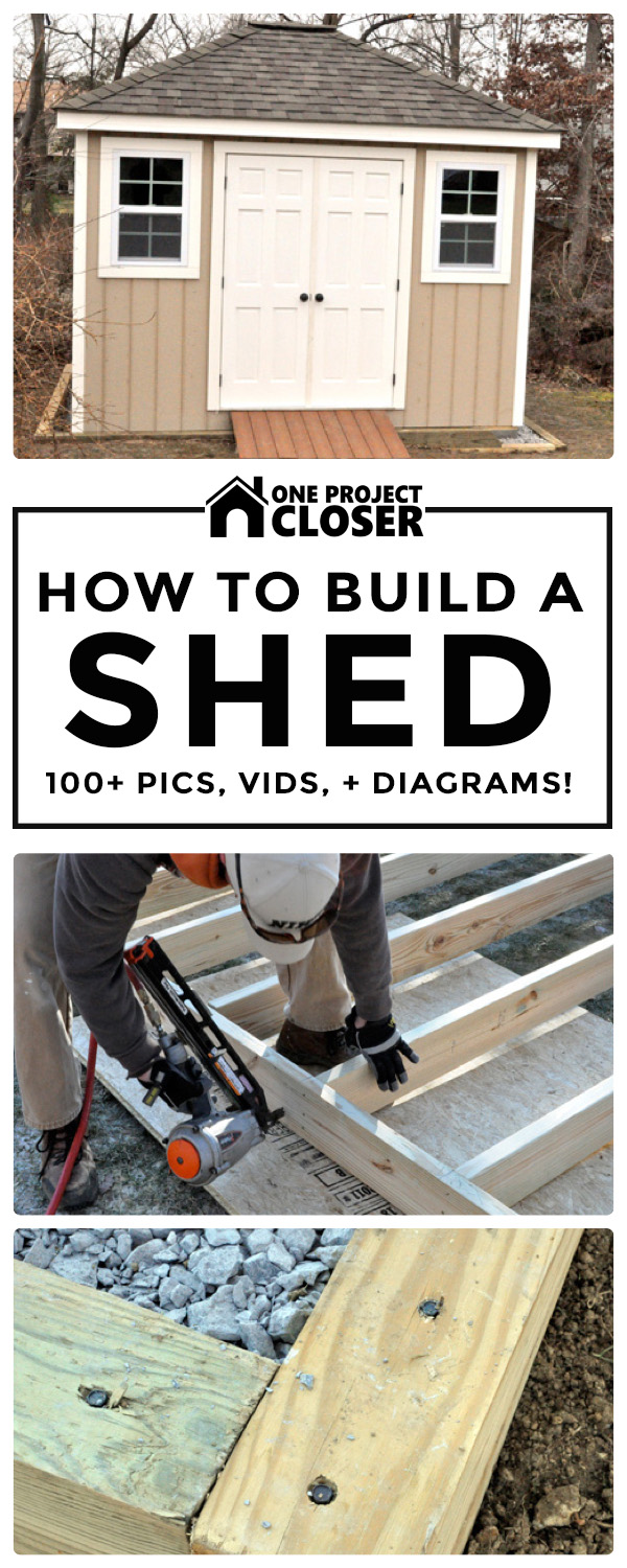
We’ve finished building three heavy-duty work benches and one of two folding wood sawhorses. Another important part of a workshop is good lumber storage. Up until now we’ve been piling boards on the floor, and it’s been a pain to keep moving them to make room for projects. Our solution is a simple wall-mounted wooden lumber rack. This article shares the instructions for building this rack.
I found the idea on Woodsmith Shop, and with a few modifications, built one that fully meets our needs.


Tools & Materials
I had one-half of a sheet of plywood left over from building the workbenches. If I didn’t have that handy, this lumber rack would cost about $55, since I would have had to purchase two whole sheets. By eliminating two of the vertical supports and being careful to minimize waste, you can build this rack with only one sheet of plywood, almost cutting the total cost in half.
Materials:
- (1.5 sheets) 3/4″ plywood (for a nicer look, consider cabinet grade plywood)
- (100) #8 x 1-1/4″ flathead screws
- (8) 3″ x 1/4″ lag screws
- (8) 1/4″ washers
- Wood glue
Tools:
Many of the cuts can be made using a circular saw. If you take that route, I suggest using guides to ensure perfectly straight cuts, because circular saws are otherwise difficult to control. We use our table saw and mitre saw, because they make the cuts much easier, since we can use built-in guides.
- Miter saw (or circ. saw)
- Table saw (or circ. saw)
- Jig saw
- Drill / driver
- Impact driver (optional)
- Clamps (optional)
- Stud finder
- Level
- Speed square
How to Build a Lumber Storage Rack
Step 1: Rip the Plywood
The entire structure is built out of plywood, and that means this project involves making a lot of rip cuts. A cabinet saw would have been really useful. I don’t have one so I made the best out of what I do have.

Here are the pieces you’ll need to cut with your table saw. I shortened my vertical supports (fourth item below) because I had to work around a garage door. Leave them at 79″ if you have the space. Also, do not rip the entire length of the plywood to make your vertical supports, because you’ll be using the excess at the end of the sheet for further shelf supports. (In other words, before cutting the vertical supports, you should cross-cut the plywood at 79″)
- (1) 3″ x 96″ (lower cleat)
- (1) 5″ x 96″ (upper cleat; requires a 45 degree angle on the table saw; more specifics below)
- (2) 6″ x 96″ (to be cut for shelf supports)
- (10) 4″ x 79″ (vertical supports)
- (1) 17″ x 24″ (this will be leftover from vertical supports, to be cut for more shelf supports)
Tip: Using these dimensions, you can have the big box store rip the plywood in half (24″ x 96″) making it easier for subsequent cuts.
The upper cleat needs to have an angled backside, from which you will hang the vertical supports. You want the width on the longest side to measure 5″, and cut it at a 45° angle. This will make the shorter side approximately 4-1/4″.
Tip from Experience: Looking back, both the upper and lower cleats could have been identical (5″ tall with a 45° angle) to better distribute the weight. The design this lumber rack is derived from used removable dowels to “lock” the vertical support in place. For that reason, the bottom cleat is more of a place holder than anything else. I didn’t incorporate the dowels, and would recommend making the bottom cleat angled, which essentially eliminates the need for the dowels in the original design.

This picture shows the top cleat after its been ripped. The top of the cleat has the angle, and the bottom is flat. It is 5″ wide at its widest point.

Step 2: Cut the Shelves
Next, cut the 6″ wide pieces with your miter saw into 6″ x 15″ rectangles. Do the same with the piece of plywood leftover from cutting your vertical supports.
Your goal is to create 15 identical shelf supports that look like this:

The easiest way to make the diagonal cut is to setup a jig for your table saw. (And no, the drill/driver wasn’t sitting there while I was cutting!)

Here’s several of the shelving supports. Note they are sitting on the table upside-down.

Tip from Experience: Consider cutting a short lip on the top of each shelf support to prevent materials from sliding off. We omitted this in our first build and have not had problems, but we think it would make a slightly better design.
In some of the pictures you’ll see that five of my shelf supports are shorter than 15″, and that’s because I had to make adjustments to work around the garage door. Just like the vertical supports, keep them full length if you have the space.
Step 3: Mark the Vertical Supports
You need to cut two notches on the vertical supports that will accommodate the upper and lower cleats. I placed my upper cleat 6″ down from the top and the lower cleat 12″ up from the bottom. With these measurements, I can have a shelf at the very bottom for sheet goods and two shelves at the top for 2×4’s and the like. Position your cleats as necessary, but work to keep approximately the same distances from top and bottom. Here’s a diagram showing where I planned the cleats and shelves:

To make things easier, I clamped all the vertical supports together and marked lines. The upper notch should measure 6″ long and the lower notch should measure 4″ long. The extra inch is to allow for clearance below the cleats.


Step 4: Cut the Notches
Now it’s time to cut the notches in the vertical supports. Using a square, the lines I just marked and a piece of scrap, I traced an outline.

Use your jig saw to cut along the lines. To make the long cut, start midway and curve onto the line like in the picture. Then cut in the opposite direction to carve out the rest. Alternately, you can drill holes at the corners big enough to fit the t-shank blade.

Remember, the upper notch needs be angled to fit the upper cleat. I used a piece of scrap from ripping the upper cleat to mark the angled line.


The angled cut in the supports fits neatly over the upper cleat.

Step 5: Glue and Screw the Shelf to the Vertical Support
Each shelf support will be sandwiched between two vertical supports. Glue and screw everything, and remember that the shelf extends away from the notches. Put four screws, staggered on each side.


Here I’ve got two of the uprights finished. You can see the shelf at the top followed closely by the second shelf. The third shelf is place at the bottom for storing sheet goods.

Step 6: Hang the Upper and Lower Cleats
The two cleats are held in place with lag screws. I didn’t have my lovely assistant, so I used some spare boards and a lot of blue tape to get things into position. I wanted the bottom of each vertical support to just barely sit on the block below. If you don’t have similar concerns, you can hang the upper cleat at whatever height is convenient. I’d recommend positioning it to keep the rack up off the floor for easier cleaning.
Remember to orient the cleat such that the angle is going into the wall (so that the vertical supports will hang from it).

Use the stud finder to locate studs and pre-drill the holes, and put a washer on each lag screw before screwing it in. Use four lag screws per cleat.

Here you can see the lower cleat in position.

Final Pictures
I’m really pleased with how this lumber rack turned out. It’s strong enough to hold my weight (and a lot more), and it keeps everything off the floor. The shelves can accommodate sheet goods and dimensional lumber of any length since they can slide left and right. Plus, they can easily be removed.
If I did this project again, I would incorporate the tips to angle the lower cleat and cut a lip into the shelf supports. Even so, this lumber rack will serve us well.


This is a comprehensive guide for how to install a tile floor (ceramic or porcelain). Below you’ll find tutorials for every step of the process, with expert knowledge and tips from professional tile contractors. Read on for links to the individual articles and recommended tools for laying tile. We hope you enjoy the series!
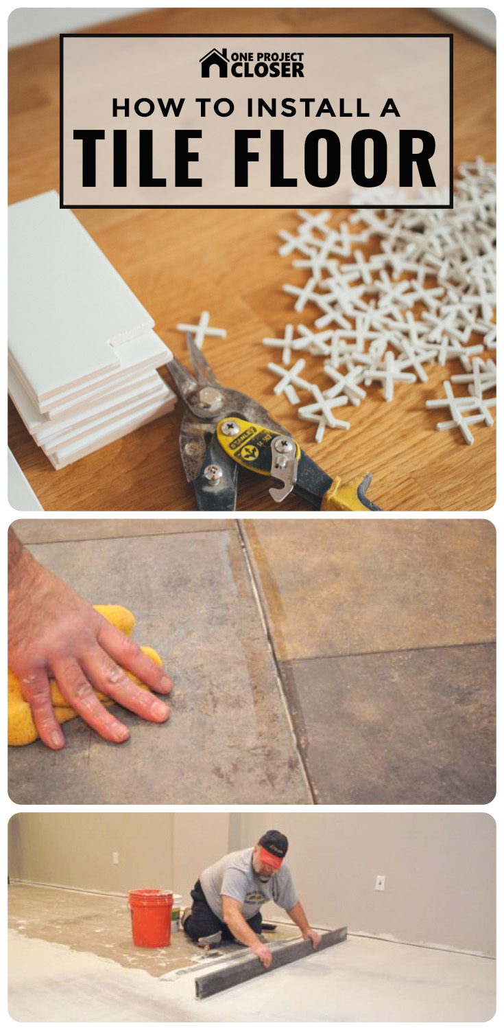
This series covers everything for installing a ceramic or porcelain tile floor, including leveling the floor, installing underlayment, marking guides, laying tile and grouting joints. Just follow the steps below, and you’ll have the know-how to install tile in almost any situation. Keep in mind that the content is provided without warranty. We strive for thorough, accurate information in describing all the steps and precautions for a job, but there is always the possibility we’ll omit something important. Use this information at your own risk.
If you find this guide for installing tile helpful, we hope you’ll spread the word, and there’s a few ways to do that. Like this article on Facebook and give it a +1. All the buttons can be found floating to the left of the article. If you own a website, feel free to share this article with your readers by linking to this page.
Not Doing it Yourself?
Before we get started, if you aren’t doing this job yourself and you live in the greater Baltimore area, we highly recommend Jim and Rich from Diamond Tile. We partnered with Jim and Rich to create this series, and you can see the quality of their work and attention to detail in every picture. Call Diamond Tile at 443-386-0065 for a free estimate.
If you’re not local to Baltimore, we suggest using Home Adviser for free quotes. They match homeowners with screened and approved local contractors who can get the job done right. Here’s the link:

Steps to Install a Tile Floor
(hover over the links to learn more about the article)
Step 1 : Checking the Subfloor
There’s a lot of confusion about what constitutes a suitable subfloor for tile and what substrates you can (and cannot) tile over. The majority of installations take place over a wood or concrete subfloor, and the two big concerns involve too much deflection and movement from seasonal changes. Read the article at that link to learn what criteria your subfloor should meet before laying tile.
Step 2: Installing Radiant Heating Wire (Optional)
Installing a heating element is a great upgrade for a tile floor, and installers are being asked to install more and more heated floors. Floors can be heated in a number of ways, and we recommend putting down radiant heat and covering it with mortar or pouring self-leveling mortar (SLM).

Step 3: Level (Flatten) the Subfloor
Professional tile contractors estimate that 90% of all remodel jobs require flattening the floor to eliminate peaks and valleys. This is an important step that is often overlooked, and an uneven floor can result in protruding corners or even broken tiles. In this article, Jim and Rich describe how to “level” an uneven wood or concrete subfloor.
Step 4: Installing Underlayment
A tile floor is only as good as the underlayment beneath it. Commonly cement board is installed over a bed of mortar. Another option is to install Schluter DITRA underlayment which serves as an uncoupling membrane, eliminating some of the major causes for cracked and delaminated tile. The guys prefer DITRA; however, it adds time and cost so they don’t use it on all jobs.
Step 5: Marking Guides
Marking accurate guides makes laying tile much easier because you can pre-cut all the tiles and eliminate the need for spacers. Jim and Rich snap chalk lines to set up a grid, and the result is perfectly straight tiles and joints.

Step 6: Laying Tile
With the proper prep work, laying tile is an easy matter. The guys pre-cut all the tiles around the perimeter, support posts, steps and doors, and they lay the tile according to their guides. Mortar in the joints is a common problem, but Jim and Rich have a great trick for eliminating excess mortar.
Step 7: Grouting Tile Joints
Grouting the joints is one of the last steps before the tile install is complete, and it really brings the tile together. This article shares how Jim and Rich grout tile joints including what tools and materials they use and a lot of pro tips.

Step 8: Installing Baseboard and Shoe Molding
Install baseboard and shoe molding involves scarf joints, inside corners (which can be cope cut), and outside corners. Quarter round can be an acceptable alternative to shoe molding if you have large gaps.
If you worked hard to sufficiently flatten the floor and make precise cuts, you can eliminate the need for shoe molding altogether.
Tools to Install Tile Flooring
A successful tile installation requires the right tools, and fortunately most of them are relatively inexpensive. The highest price item you’ll need is a tile saw, and this can be rented at your local home improvement center. This list doesn’t include materials like mortar or grout. Check the individual tutorial for material details.
 Other tools you need include:
- Chalk line
- Tape measure
- Level
- Wax pencil
- Foxtail brush
- Hammer
- Utility knife
- Screed or straight-edge
- Jamb saw (or something similar)
- Corded drill with mixing paddle
- Buckets
- Tile saw (or something similar)
- Notched trowel
- Flat trowel
- Grout float
- Sponge
Where to Purchase Ceramic or Porcelain Tile
 The old adage that “you get what you pay for” is true with tile. High quality tile is manufactured to be more uniform in size, and that’s important for aligning tile with consistent grout joints. The tile we show here was purchased through a local tile distributor, and we suggest you do the same.
Depending on what you select and where the tile is manufactured, expect to pay at least $3 per square foot. Be sure to purchase boxes with the same batch number or consecutive batch numbers. This helps ensure a consistent color and pattern.
Big box stores also carry tile. However, they usually offer seconds of quality brands and mixed batches. This makes it frustratingly difficult to maintain a uniform look and pattern, especially with smaller grout joints. DIY centers usually have better prices and often offer promotions that small distributors can’t match. If price is your main concern, be sure to check out list our Home Depot Coupons and Lowe’s Coupons before you buy.
Did You Find This Guide Useful?
If you found this guide useful, we’d really appreciate it if you’d click the Facebook “Like” or Google “+1” buttons over there on the left. They let others know that these guides are helpful! Thanks so much!
Today we’re featuring a guest article by Ken from The Joy of Moldings
Jennifer’s kitchen is getting a top to bottom molding makeover. I just installed the crown molding and door trim (a Greek Revival eared architrave style), but still have the baseboard and wainscoting to go. Since I get so many questions at The Joy of Moldings.com about how to paint crown moldings, I thought I’d share my painting techniques with One Project Closer readers.

Project Price & Materials
- Crown Molding Materials From Lowes: $211.75
- Primer: $30.74 Sherwin Williams Wall & Wood Primer (this primer will last for most of the house)
- Trim Paint: $65.99 Benjamin Moore, White Dove OC-17, Satin Finish (This will last us for most of the house as well)
- Flotrol: $7.00 Paint Additive
Grand total: $315.48 + tax
High-Resolution Painting
My goal when painting moldings is to make them look like they are an integrated part of the home’s architecture, and not just sticks of painted moldings nailed to the walls. To achieve that solid look on both moldings and walls, I’ve developed a series of preparation and painting steps that consistently give me what I call a high-resolution paint job
How to Prepare the Crown Molding for Paint
I’ve already spackled all the nail holes, so the spackling is dry and ready to sand. I work in small sections from top to bottom to make sure I don’t miss anything. When I’ve finished a section I run my hand over it to feel for imperfections that I can’t see. If I can feel an imperfection, then it will probably show through the finish coats of paint, so it gets sanded.


Prime the Whole Crown Molding
All of those nail holes and other places I’ve spackled have to be covered over with primer or else they will show up as little rough spots through the final coat of paint. So I just prime the whole crown molding.


Caulk The Crown Molding
A common complaint about painting crown molding is when someone runs a fat bead of caulk across the top and bottom of their crown molding, and then wonders why they can’t cut-in a straight line of wall paint against the crown.
The not-so-secret secret to painting straight lines against your crown is to do a really great job caulking it.


Caulking is one of the most important steps in bringing my crown to an ever-increasing state of perfection. This is a monotonous task, so I just put on some music, make sure I’ve got lots of Jennifer’s, yummy home-made snacks at hand, and try to make it as enjoyable as possible.


How to Paint the Crown Molding
Some folks love to paint while others would rather have a root canal without Novocaine. If you’re of the later group, these tips might help ease the pain.

I always use a paint leveler/extender when painting moldings. Always. It extends the time you can work with the paint before it starts to tack up, and that leaves me with fewer brush strokes in the finish coat.

When doing brush work, I never, ever work out of the paint can or out of a large paint tray. Better to run back and add more paint to a small tray than to let the paint get sticky in a large one.

Painting Sequence
My arm just sort of goes on auto-pilot when painting crown. That’s because I have a sequence I follow that ensures I paint quickly enough to maintain a wet edge to the paint, and get that give me the best finish possible.

I can not maintain a good wet edge if I’m concerned about getting paint on the walls or ceiling, because it makes me paint too slowly.


I’ll put a bit of primer over the overpaint before I paint the walls.

It’s a race between painting quickly yet in control to maintain a very wet edge — so the crown has a perfectly blended finish coat — and painting so slowly that I leave brush strokes and start and stop marks in the finish coat.

Two coats are better than one. I always paint two coats on my trim, ceilings and walls (even if the manufacturer says it covers in one) — it’s the only way to get the true color of the paint.
Paint The Ceiling


When I get just a little bit of overpaint on the crown, I use a putty knife and damp rag to remove it.


Paint the Walls
The only way to paint perfect lines up to the moldings is to paint by hand with a good brush. Masking off the moldings with tape will always end in frustration, because the paint seeps under the tape and gets all over the moldings.

The trick is to not get too much paint on your brush. Put a bit on your brush, brush that paint onto the wall near the trim to act as a little paint reservoir, and then work the paint from the wall up against the molding. You’ll develop a feel for it and get faster with practice.


Above: This door trim style is called an eared architrave, and I built it using stock materials from Lowes Home Improvement for a grand total of $74.60.

And that’s all there is to it!
To Review: Ken’s Most Important Things About Painting Crown Molding
- Never paint crown molding before installing
- Always paint two coats
- Paint the crown molding first, then ceiling and then walls
- Apply a unifying coat of primer, even to pre-primed crown
- Use good paint like Benjamin Moore Satin Impervo
- Use a paint leveler/extender to increase your working time with the paint and remove brush strokes
- Use good brushes like Purdy or Wooster
- Move everything out of your way — clear the decks
- Use a small cut-in tray and don’t put too much paint in it
- Always keep your wet edge in mind
- Cover your paint tray and brush with a damp rag when not in use
- Turn the heat down in the house
- Feather the overpaint that gets on the walls
- Paint in sections
- Use finish stokes
- Never use blue tape on moldings when painting the walls; free-hand the paint from wall to the molding
You can keep up with our molding makeover progress at The Joy of Moldings. Good luck painting your own crown moldings!
Cheers,
Ken & Jennifer